S/UNI®-8x155 ASSP Telecom Standard Product Data Sheet
Released
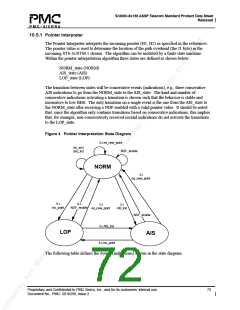
10.5.1 Pointer Interpreter
The Pointer Interpreter interprets the incoming pointer (H1, H2) as specified in the references.
The pointer value is used to determine the location of the path overhead (the J1 byte) in the
incoming STS-3c/STM-1 stream. The algorithm can be modeled by a finite state machine.
Within the pointer interpretation algorithm three states are defined as shown below:
NORM_state (NORM)
AIS_state (AIS)
LOP_state (LOP)
The transition between states will be consecutive events (indications), e.g., three consecutive
AIS indications to go from the NORM_state to the AIS_state. The kind and number of
consecutive indications activating a transition is chosen such that the behavior is stable and
insensitive to low BER. The only transition on a single event is the one from the AIS_state to
the NORM_state after receiving a NDF enabled with a valid pointer value. It should be noted
that, since the algorithm only contains transitions based on consecutive indications, this implies
that, for example, non-consecutively received invalid indications do not activate the transitions
to the LOP_state.
Figure 4 Pointer Interpretation State Diagram
3 x eq_new_point
inc_ind /
NDF_enable
dec_ind
NORM
3 x
eq_new_point
8 x
8 x
3 x
3 x
inv_point
NDF_enable
eq_new_point
AIS_ind
NDF_enable
3 x AIS_ind
8 x inv_point
LOP
AIS
The following table defines the events (indications) shown in the state diagram.
Proprietary and Confidential to PMC-Sierra, Inc., and for its customers’ internal use.
Document No.: PMC- 2010299, Issue 2
72

 PMC [ PMC-SIERRA, INC ]