S/UNI®-8x155 ASSP Telecom Standard Product Data Sheet
Released
Table 1 Pointer Interpreter Event (Indications) Description
Event (Indication)
norm_point
Description
disabled NDF + ss + offset value equal to active offset
NDF_enable
enabled NDF + ss + offset value in range of 0 to 782 or
enabled NDF + ss, if NDFPOR bit is set (Note that the current pointer is not
updated by an enabled NDF if the pointer is out of range).
AIS_ind
inc_ind
H1 = 'hFF, H2 = 'hFF
disabled NDF + ss + majority of I bits inverted + no majority of D bits inverted +
previous NDF_enable, inc_ind or dec_ind more than 3 frames ago
dec_ind
disabled NDF + ss + majority of D bits inverted + no majority of I bits inverted +
previous NDF_enable, inc_ind or dec_ind more than 3 frames ago
inv_point
new_point
not any of above (i.e., not norm_point, and not NDF_enable, and not AIS_ind,
and not inc_ind and not dec_ind)
disabled_NDF + ss + offset value in range of 0 to 782 but not equal to active
offset
inc_req
dec_req
Notes
majority of I bits inverted + no majority of D bits inverted
majority of D bits inverted + no majority of I bits inverted
1. The active offset is defined as the accepted current phase of the SPE (VC) in the NORM_state and is
undefined in the other states.
2. Enabled NDF is defined as the following bit patterns: 1001, 0001, 1101, 1011, 1000.
3. Disabled NDF is defined as the following bit patterns: 0110, 1110, 0010, 0100, 0111.
4. The remaining six NDF codes (0000, 0011, 0101, 1010, 1100, 1111) result in an inv_point indication.
5. The ss bits are unspecified in SONET and has bit pattern 10 in SDH
6. The use of ss bits in definition of indications may be optionally disabled.
7. The requirement for previous NDF_enable, inc_ind or dec_ind be more than 3 frames ago may be
optionally disabled.
8. The new_point is also an inv_point.
9. LOP is not declared if all the following conditions exist:
Sꢀ The received pointer is out of range (>782)
Sꢀ The received pointer is static
Sꢀ The received pointer can be interpreted, according to majority voting on the I and D bits, as a
positive or negative justification indication, after making the requested justification, the received
pointer continues to be interpretable as a pointer justification. When the received pointer returns
to an in-range value, the S/UNI-8x155 will interpret it correctly.
10. LOP will exit at the third frame of a three frame sequence consisting of one frame with NDF enabled
followed by two frames with NDF disabled, if all three pointers have the same legal value.
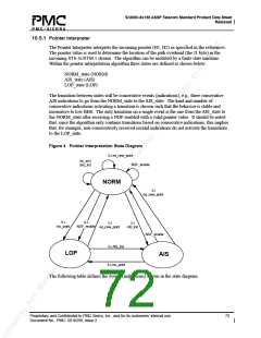
The transitions indicated in the state diagram are defined in the following table.
Table 2 Pointer Interpreter Transition Description
Transition
inc_ind/dec_ind
Description
offset adjustment (increment or decrement indication)
3 x eq_new_point
three consecutive equal new_point indications
Proprietary and Confidential to PMC-Sierra, Inc., and for its customers’ internal use.
Document No.: PMC- 2010299, Issue 2
73

 PMC [ PMC-SIERRA, INC ]