S/UNI®-8x155 ASSP Telecom Standard Product Data Sheet
Released
10.5.3 Error Monitor
The Error Monitor Block contains two 16-bit counters that are used to accumulate path BIP-8
errors (B3), and far end block errors (FEBEs). The contents of the two counters may be
transferred to holding registers, and the counters reset under microprocessor control.
Path BIP-8 errors are detected by comparing the path BIP-8 byte (B3) extracted from the
current frame, to the path BIP-8 computed for the previous frame.
FEBEs are detected by extracting the 4-bit FEBE field from the path status byte (G1). The legal
range for the 4-bit field is between 0000 and 1000, representing zero to eight errors. Any other
value is interpreted as zero errors.
Path RDI alarm is detected by extracting bit 5 of the path status byte. The PRDI signal is set
high when bit 5 is set high for five/ten consecutive frames. PRDI is set low when bit 5 is low
for five/ten consecutive frames. Auxiliary RDI alarm is detected by extracting bit 6 of the path
status byte. The Auxiliary RDI alarm is indicated when bit 6 is set high for five/ten consecutive
frames. The Auxiliary RDI alarm is removed when bit 6 is low for five/ten consecutive frames.
The Enhanced RDI alarm is detected when the enhanced RDI code in bits 5,6,7 of the path
status byte indicates the same error codepoint for five/ten consecutive frames. The Enhanced
RDI alarm is removed when the enhanced RDI code in bits 5,6,7 of the path status byte
indicates the same non error codepoint for five/ten consecutive frames. The ERDII maskable
interrupt is set high when bits 5, 6 & 7 of the path status byte (G1) byte are set to a new
codepoint for five or ten consecutive frames. The ERDIV[2:0] signal reflects the state of the
filtered ERDI value (G1 byte bits 5, 6, & 7).
10.6 Receive ATM Cell Processor (RXCP)
The Receive ATM Cell Processor (RXCP) performs ATM cell delineation, provides cell filtering
based on idle/unassigned cell detection and HCS error detection, and performs ATM cell
payload descrambling.
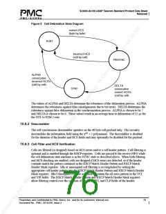
10.6.1 Cell Delineation
Cell Delineation is the process of framing to ATM cell boundaries using the header check
sequence (HCS) field found in the cell header. The HCS is a CRC-8 calculation over the first 4
octets of the ATM cell header. When performing delineation, correct HCS calculations are
assumed to indicate cell boundaries. Cells are assumed to be byte-aligned to the synchronous
payload envelope. The cell delineation algorithm searches the 53 possible cell boundary
candidates individually to determine the valid cell boundary location. While searching for the
cell boundary location, the cell delineation circuit is in the HUNT state. When a correct HCS is
found, the cell delineation state machine locks on the particular cell boundary, corresponding to
the correct HCS, and enters the PRESYNC state. The PRESYNC state validates the cell
boundary location. If the cell boundary is invalid, an incorrect HCS will be received within the
next DELTA cells, at which time a transition back to the HUNT state is executed. If no HCS
errors are detected in this PRESYNC period, the SYNC state is entered. While in the SYNC
state, synchronization is maintained until ALPHA consecutive incorrect HCS patterns are
detected. In such an event a transition is made back to the HUNT state. The state diagram of
the delineation process is shown in Figure 5.
Proprietary and Confidential to PMC-Sierra, Inc., and for its customers’ internal use.
Document No.: PMC- 2010299, Issue 2
75

 PMC [ PMC-SIERRA, INC ]