S/UNI®-8x155 ASSP Telecom Standard Product Data Sheet
Released
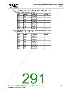
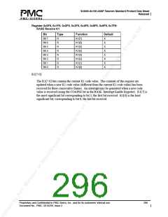
Register 0x0F1, 0x1F1, 0x2F1, 0x3F1, 0x4F1, 0x5F1, 0x6F1, 0x7F1:
RASE SD Declaring Threshold LSB
Bit
Type
R/W
R/W
R/W
R/W
R/W
R/W
R/W
R/W
Function
SDDTH[7]
SDDTH[6]
SDDTH[5]
SDDTH[4]
SDDTH[3]
SDDTH[2]
SDDTH[1]
SDDTH[0]
Default
Bit 7
Bit 6
Bit 5
Bit 4
Bit 3
Bit 2
Bit 1
Bit 0
0
0
0
0
0
0
0
0
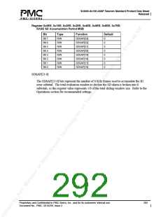
Register 0x0F2, 0x1F2, 0x2F2, 0x3F2, 0x4F2, 0x5F2, 0x6F2, 0x7F2:
RASE SD Declaring Threshold MSB
Bit
Type
Function
Unused
Unused
Unused
Unused
SDDTH[11]
SDDTH[10]
SDDTH[9]
SDDTH[8]
Default
Bit 7
Bit 6
Bit 5
Bit 4
Bit 3
Bit 2
Bit 1
Bit 0
X
X
X
X
0
0
0
0
R/W
R/W
R/W
R/W
SDDTH[11:0]:
The SDDTH[11:0] value determines the threshold for the declaration of the SD alarm. The
SD alarm is declared when the number of B2 errors accumulated during an evaluation
window is greater than or equal to the SDDTH[11:0] value. Refer to the Operations section
for the recommended settings.
Proprietary and Confidential to PMC-Sierra, Inc., and for its customers’ internal use.
Document No.: PMC- 2010299, Issue 2
294

 PMC [ PMC-SIERRA, INC ]