February, 2007
Strapping Signals
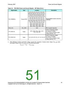
3.4.4
Strapping Signals
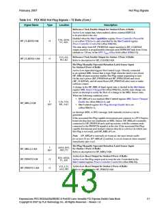
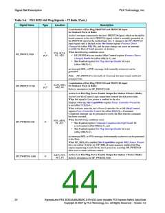
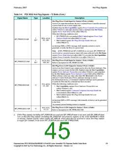
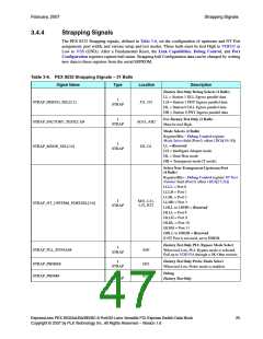
The PEX 8532 Strapping signals, defined in Table 3-6, set the configuration of upstream and NT Port
assignment, port width, and various setup and test modes. These balls must be tied High to VDD33 or
Low to VSS (GND). After a Fundamental Reset, the Link Capabilities, Debug Control, and Port
Configuration registers capture ball status. Strapping ball Configuration data can be changed by writing
new data to these registers from the serial EEPROM.
Table 3-6. PEX 8532 Strapping Signals – 31 Balls
Signal Name
Type
Location
Description
Factory Test Only Debug Selects (2 Balls)
LL = Station 1 DLL Egress parallel data
LH = Station 1 PHY Ingress parallel data
HL = Station 0 DLL Egress parallel data
HH = Station 0 PHY Ingress parallel data
I
STRAP_DEBUG_SEL[2:1]
J31, J32
STRAP
For Factory Test Only (2 Balls)
Must be tied High.
I
STRAP_FACTORY_TEST[2:1]#
STRAP_MODE_SEL[1:0]
AG31, AH2
H2, G1
STRAP
Mode Selects (2 Balls)
Register/Bits – Debug Control register
Mode Select field (Port 0, offset 1DCh[19:18])
LL = Reserved
LH = Intelligent Adapter mode
HL = Dual-Host mode
I
STRAP
HH = Transparent mode (T mode)
Select Non-Transparent Upstream Port
(4 Balls)
Register/Bits – Debug Control register NT Port
Number field (Port 0, offset 1DCh[27:24])
LLLL = Port 0
LLLH = Port 1
LLHL = Port 2
LLHH = Port 3
LHLL to LHHH = Reserved
HLLL = Port 8
I
M31, L31,
L32, K32
STRAP_NT_UPSTRM_PORTSEL[3:0]
STRAP
HLLH = Port 9
HLHL = Port 10
HLHH = Port 11
HHLL to HHHH = Reserved
If NT Port is not used, set to HHHH.
Factory Test Only PLL Bypass Mode Select
When tied Low, PLL Bypass mode is selected.
Pull up to VDD33A through a 5K-Ohm resistor.
I
STRAP_PLL_BYPASS#
AH1
STRAP
Factory Test Only Probe Mode Select
When tied Low, Probe mode is enabled.
I
STRAP_PROBE#
STRAP_PROM#
H32
K31
STRAP
Debug
Factory Test Only
I
STRAP
ExpressLane PEX 8532AA/BA/BB/BC 8-Port/32-Lane Versatile PCI Express Switch Data Book
Copyright © 2007 by PLX Technology, Inc. All Rights Reserved – Version 1.6
25

 PLX [ PLX TECHNOLOGY ]