Signal Ball Description
PLX Technology, Inc.
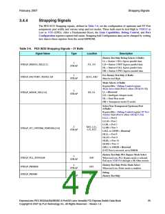
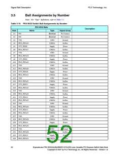
Table 3-6. PEX 8532 Strapping Signals – 31 Balls (Cont.)
Signal Name
Type
Location
Description
Strapping Signals to Select Number of Lanes
in Station 0, Ports 0, 1, 2, 3 (5 Balls)
Register/Bits – Port Configuration register Port
Configuration field (Port 0, offset 224h[4:0])
Note: x0 indicates the port is not enabled.
LLLLL = x4, x4, x4, x4
LLLLH = x16, x0, x0, x0
LLLHL = x8, x8, x0, x0
AC32, AC31,
AD32, AD31,
AE32
I
STRAP_STN0_PORTCFG[4:0]
STRAP
LLLHH = x8, x4, x4, x0
LLHLL = x8, x4, x2, x2
LLHLH = x8, x2, x2, x4
LLHHL = x8, x2, x4, x2
All other configurations are reserved and default
to x4, x4, x4, x4.
Strapping Signals to Select Number of Lanes
in Station 1, Ports 8, 9, 10, 11 (5 Balls)
Register/Bits – Port Configuration register Port
Configuration field (Port 8, offset 224h[4:0])
Note: x0 indicates the port is not enabled.
LLLLL = x4, x4, x4, x4
I
P32, P31, N32, LLLLH = x16, x0, x0, x0
STRAP_STN1_PORTCFG[4:0]
N31, M32
STRAP
LLLHL = x8, x8, x0, x0
LLLHH = x8, x4, x4, x0
LLHLL = x8, x4, x2, x2
LLHLH = x8, x2, x2, x4
LLHHL = x8, x2, x4, x2
All other configurations are reserved and default
to x4, x4, x4, x4.
Test Mode Selects (4 Balls)
Factory Test Only
Register – Physical Layer Test
(Ports 0 and 8, offset 228h)
I
H33, H34,
G33, G34
STRAP_TESTMODE[3:0]
STRAP
HHHH = Default (Test Modes are disabled)
Strapping Signals to Select Upstream Port
(4 Balls)
Register/Bits – Debug Control register
Upstream Port Number field
(Port 0, offset 1DCh[11:8])
LLLL = Port 0
LLLH = Port 1
LLHL = Port 2
LLHH = Port 3
I
STRAP_UPSTRM_PORTSEL[3:0]
N4, M4, N3, M3
STRAP
LHLL to LHHH = Reserved
HLLL = Port 8
HLLH = Port 9
HLHL = Port 10
HLHH = Port 11
HHLL to HHHH = Reserved
26
ExpressLane PEX 8532AA/BA/BB/BC 8-Port/32-Lane Versatile PCI Express Switch Data Book
Copyright © 2007 by PLX Technology, Inc. All Rights Reserved – Version 1.6

 PLX [ PLX TECHNOLOGY ]