February, 2007
Power and Ground Signals
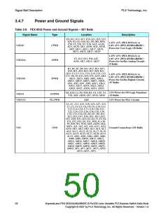
Table 3-9. PEX 8532 Power and Ground Signals – 367 Balls (Cont.)
Signal Name
Type
Location
Description
N13, N14, N15, N16, N17, N18, N19,
N20, N21, N22, P13, P14, P15, P16, P17,
P18, P19, P20, P21, P22, R13, R14, R15,
R16, R17, R18, R19, R20, R21, R22,
T13, T14, T15, T16, T17, T18, T19, T20,
T21, T22, U13, U14, U15, U16, U17,
U18, U19, U20, U21, U22, V13, V14,
V15, V16, V17, V18, V19, V20, V21,
V22, W13, W14, W15, W16, W17, W18,
W19, W20, W21, W22, Y13, Y14, Y15,
Y16, Y17, Y18, Y19, Y20, Y21, Y22,
AA13, AA14, AA15, AA16, AA17,
AA18, AA19, AA20, AA21, AA22,
AB13, AB14, AB15, AB16, AB17,
AB18, AB19, AB20, AB21, AB22
Thermal-Ball Ground Connections
(100 Balls)
VSS_THERMAL
Thermal-GND
VSSA_PLL
PLL_GND
Supply
AH4
PLL Ground Connection
SerDes Termination Supply
for Station 0a (8 Balls)
Tied to SerDes termination supply
voltage (typically 1.5V).
AP33, AP29, AP25, AP21, AP17,
AP13, AP9, AP5
VTT_PEX[7:0]
SerDes Termination Supply
for Station 1a (8 Balls)
Tied to SerDes termination supply
voltage (typically 1.5V).
VTT_PEX[15:8]
Supply
A33, A29, A25, A21, A17, A13, A9, A5
a. PEX_PETn/p[x] SerDes termination voltage controls the transmitter Common mode voltage (V
) value
TX–CM
and output voltage swing (V
), per the following formula:
TX–DIFFp
V
= V
– V
TT TX–DIFFp
TX-CM
ExpressLane PEX 8532AA/BA/BB/BC 8-Port/32-Lane Versatile PCI Express Switch Data Book
Copyright © 2007 by PLX Technology, Inc. All Rights Reserved – Version 1.6
29

 PLX [ PLX TECHNOLOGY ]