Hot Plug Support
PLX Technology, Inc.
9.5
Hot Plug Board Insertion and Removal Process
Table 9-4 defines the board insertion procedure supported by the PEX 8532. Table 9-5 defines the board
removal procedure.
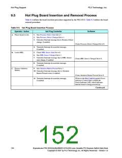
Table 9-4. Hot Plug Board Insertion Process
Operator / Action
Hot Plug Controller
Software
A. Places board in slot.
1. Sets Presence Detect State bit to 1.
2. Sets Presence Detect Changed bit to 1.
3. Generates Interrupt message due to Presence Detect
change, if enabled.
Clears Presence Detect Changed bit to 0.
4. Transmits Interrupt de-assertion message,
if enabled.
B. Locks MRL.
5. Clears MRL Sensor State bit to 0.
6. Sets MRL Sensor Changed bit to 1.
7. Generates Interrupt message due to MRL Sensor
Clears MRL Sensor Changed bit to 0.
state change, if enabled.
8. Transmits Interrupt de-assertion message,
if enabled.
C. Presses Attention
9. Sets Attention Button Pressed bit to 1.
Button.
10. Generates Interrupt message due to Attention
Button Pressed event, if enabled.
Clears Attention Button Pressed bit to 0.
11. Transmits Interrupt de-assertion message,
Writes to the Slot Control register Power
Indicator Control field, to blink the
Power Indicator LED, which indicates
that the board is being powered up.
if enabled.
Continued …
130
ExpressLane PEX 8532AA/BA/BB/BC 8-Port/32-Lane Versatile PCI Express Switch Data Book
Copyright © 2007 by PLX Technology, Inc. All Rights Reserved – Version 1.6

 PLX [ PLX TECHNOLOGY ]