Software Architecture
PLX Technology, Inc.
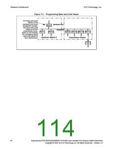
7.3.2.2
Non-Transparent Mode Registers
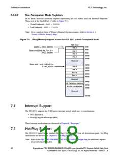
In NT mode, there are additional registers representing the NT Virtual and Link Interface endpoints.
These exist at the fixed offsets of (refer to Figure 7-5):
• Virtual Endpoint – BAR0 + 10000h
• Link Endpoint – BAR0 + 11000h
Note: For a complete listing of Memory-Mapped Register accesses, refer to Section A.1,
“Serial EEPROM Memory Map.”
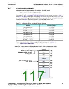
Figure 7-5. Using Memory-Mapped Access for PEX 8532 in Non-Transparent Mode
PEX 8532
0 KB
BAR0 = 0100_0000h
Port 0
4 KB
Base and Limit for Port 0 =
Port 1
0100_0020h
8 KB
Port 2
12 KB
Port 3
16 KB
Reserved
Base and Limit for Port 8 =
32 KB
Port 8
0100_8020h
36 KB
Port 9
40 KB
Port 10
44 KB
Port 11
48 KB
Reserved
64 KB
NT Port Virtual Interface
68 KB
NT Port Link Interface
72 KB
Reserved
128 KB
7.4
Interrupt Support
The PEX 8532 supports the PCI Express interrupt model, which uses two mechanisms:
• INTx Emulation
• Message Signaled Interrupt (MSI)
These interrupt mechanisms are discussed in Chapter 6, “Interrupts.”
7.5
Hot Plug Support
The PEX 8532 supports the standard Hot Plug Controller (HPC) on all downstream ports. Hot Plug
mechanisms are discussed in Chapter 9, “Hot Plug Support.”
Note: Refer to the PEX 85XX EEPROM – PEX 8532/8524/8516 Design Note for additional register
programming information.
96
ExpressLane PEX 8532AA/BA/BB/BC 8-Port/32-Lane Versatile PCI Express Switch Data Book
Copyright © 2007 by PLX Technology, Inc. All Rights Reserved – Version 1.6

 PLX [ PLX TECHNOLOGY ]