Philips Semiconductors
Preliminary specification
Sound fader control circuit
for car radios
TEA6330T
Low level control fader is included independent of the
volume controls, because the TEA6330T has four driver
outputs (for front and rear).
FUNCTIONAL DESCRIPTION
2
This bipolar IC is an I C-bus controlled sound/volume
controller for car radios including fader function and the
possibility of an external equalizer. The sound signal
setting is performed by resistor chains in combination with
multi-input operational amplifiers. The advantages of this
principle are the combination of low noise, low distortion
and a high dynamic range. The separated volume controls
of the left and the right channel make the balance control
possible. The value and the characteristic of the balance is
An extra mute position for the front, the rear or for all
channels is built in. The last function may be used for
muting during preset selection. No external interface is
required between the microcomputer and this circuit, for all
switching and controlling functions are controllable via the
2
two-wire I C-bus.
The separate mute-pin allows to switch the fader into mute
2
controlled via the I C-bus.
2
position without using the I C-bus.
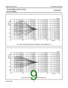
The contour function is performed by setting an extra bass
control and optional treble, depending on the actual
volume position. Its switching points and its range are also
The on chip power-on reset sets the TEA6330T into the
general mute mode.
2
controllable via the I C-bus.
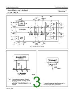
An interface is assigned behind the volume control to
loop-in an equalizer (Fig.2). In this case the treble control
is switched off, and the bass control can be used to set the
contour.
LIMITING VALUES
In accordance with the Absolute Maximum System (IEC 134). Ground pins 3 and 10 connected together.
SYMBOL PARAMETER MIN. MAX.
10
UNIT
V
P
supply voltage (pin 18)
total power dissipation
storage temperature range
0
0
V
P
700
mW
°C
°C
V
tot
T
T
−55
−40
−
150
stg
operating ambient temperature range
electrostatic handling* for all pins
electrostatic handling** for all pins
85
amb
V
±300
±4000
ESD
−
V
* Equivalent to discharging a 200 pF capacitor through a 0 Ω series resistor.
** Equivalent to discharging a 100 pF capacitor through a 1.5 kΩ series resistor.
January 1992
5

 NXP [ NXP ]