Philips Semiconductors
Product specification
Enhanced octal universal asynchronous
receiver/transmitter (Octal UART)
SCC2698B
clock is used instead of a crystal, X1 must be driven and X2 left
floating as shown in Figure 9. The clock serves as the basic timing
reference for the baud rate generator (BRG), the counter/timer, and
other internal circuits. A clock frequency, within the limits specified in
the electrical specifications, must be supplied even if the internal
BRG is not used.
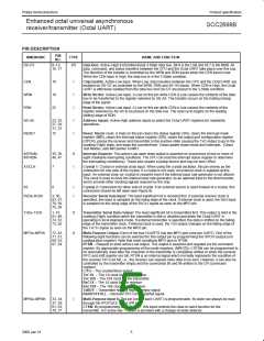
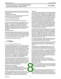
Table 1.
Register Addressing
Units A and B
Units E and F
WRITE
A5 A4 A3 A2 A1 A0 READ (RDN=0)
(WRN=0)
WRITE
(WRN=0)
A5 A4 A3 A2 A1 A0 READ (RDN=0)
0
0
0
0
0
0
0
0
0
0
0
0
0
0
0
0
0
0
0
0
0
0
0
0
0
0
0
0
0
0
0
0
0
0
0
0
0
0
0
0
1
1
1
1
1
1
1
1
0
0
0
0
1
1
1
1
0
0
0
0
1
1
1
1
0
0
1
1
0
0
1
1
0
0
1
1
0
0
1
1
0
1
0
1
0
1
0
1
0
1
0
1
0
1
0
1
MR1a, MR2a
SRa
BRG Test
RHRa
IPCRA
ISRA
MR1a, MR2a
CSRa
CRa
THRa
ACRA
1
1
1
1
1
1
1
1
1
1
1
1
1
1
1
1
0
0
0
0
0
0
0
0
0
0
0
0
0
0
0
0
0
0
0
0
0
0
0
0
1
1
1
1
1
1
1
1
0
0
0
0
1
1
1
1
0
0
0
0
1
1
1
1
0
0
1
1
0
0
1
1
0
0
1
1
0
0
1
1
0
1
0
1
0
1
0
1
0
1
0
1
0
1
0
1
MR1e, MR2e
SRe
Reserved
RHRe
IPCRC
ISRC
CTUC
CTLC
MR1e, MR2e
CSRe
CRe
THRe
ACRC
IMRC
CTPUC
CTPLC
MR1f, MR2f
CSRf
2
1
IMRA
CTUA
CTLA
CTPUA
CTPLA
MR1b, MR2b
CSRb
MR1b, MR2b
SRb
MR1f, MR2f
SRf
2
1
1X/16X Test
CRb
Reserved
CRf
RHRb
Reserved
THRb
Reserved
RHRf
Reserved
THRf
Reserved
1
1
1
1
Input port A
Start C/T A
Stop C/T A
OPCRA
Reserved
Reserved
Input port C
Start C/T C
Stop C/T C
OPCRC
Reserved
Reserved
1
1
1
1
Units C and D
Units G and H
0
0
0
0
0
0
0
0
0
0
0
0
0
0
0
0
1
1
1
1
1
1
1
1
1
1
1
1
1
1
1
1
0
0
0
0
0
0
0
0
1
1
1
1
1
1
1
1
0
0
0
0
1
1
1
1
0
0
0
0
1
1
1
1
0
0
1
1
0
0
1
1
0
0
1
1
0
0
1
1
0
1
0
1
0
1
0
1
0
1
0
1
0
1
0
1
MR1c, MR2c
MR1c, MR2c
CSRc
CRc
THRc
ACRB
1
1
1
1
1
1
1
1
1
1
1
1
1
1
1
1
1
1
1
1
1
1
1
1
1
1
1
1
1
1
1
1
0
0
0
0
0
0
0
0
1
1
1
1
1
1
1
1
0
0
0
0
1
1
1
1
0
0
0
0
1
1
1
1
0
0
1
1
0
0
1
1
0
0
1
1
0
0
1
1
0
1
0
1
0
1
0
1
0
1
0
1
0
1
0
1
MR1g, MR2g
MR1g, MR2g
CSRg
CRg
THRg
ACRD
SRc
SRg
1
1
Reserved
RHRc
IPCRB
ISRB
Reserved
RHRg
IPCRD
ISRD
IMRB
IMRD
CTUB
CTLB
CTPUB
CTPLB
MR1d, MR2d
CSRd
CTUD
CTLD
CTPUD
CTPLD
MR1h, MR2h
CSRh
MR1d, MR2d
SRd
MR1h, MR2h
SRh
1
1
Reserved
CRd
Reserved
CRh
RHRd
Reserved
THRd
Reserved
RHRh
Reserved
THRh
Reserved
1
1
1
1
Input port B
Start C/T B
Stop C/T B
OPCRB
Reserved
Reserved
Input port D
Start C/T D
Stop C/T D
OPCRD
Reserved
Reserved
1
1
1
1
NOTE:
1. Reserved registers should never be read during normal operation since they are reserved for internal diagnostics.
ACR
CR
CSR
CTL
=
=
=
=
Auxiliary control register
Command register
Clock select register
Counter/timer lower
SR
THR
RHR
=
=
=
Status Register
Tx holding register
Rx holding register
IPCR = Input port change register
CTPL = Counter/timer preset lower register
CTU Counter/timer upper
CTPU = Counter/timer preset upper register
MR Mode register
ISR
IMR
=
=
Interrupt status register
Interrupt mask register
=
OPCR= Output port configuration register
=
2. See Table 5 for BRG Test frequencies in this data sheet, and “Extended baud rates for SCN2681, SCN68681, SCC2691, SCC2692, SCC68681
and SCC2698B” Philips Semiconductors ICs for Data Communications, IC-19, 1994.
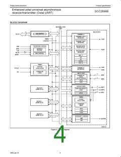
used as a timer to produce a 16X clock for any other baud rate by
BRG
counting down the crystal clock or an external clock. The clock
selectors allow the independent selection, by the receiver and
transmitter, of any of these baud rates or an external timing signal.
The baud rate generator operates from the oscillator or external
clock input and is capable of generating 26 commonly used data
communications baud rates ranging from 50 to 115.2K baud.
Thirteen of these are available simultaneously for use by the
receiver and transmitter. Eight are fixed, and one of two sets of five
can be selected by programming ACR[7]. The clock outputs from
the BRG are at 16X the actual baud rate. The counter/timer can be
Counter–Timer
The four Counter/Timers are programmable 16 bit dividers that are
used for generating miscellaneous clocks or generating timeout
7
2000 Jan 31

 NXP [ NXP ]