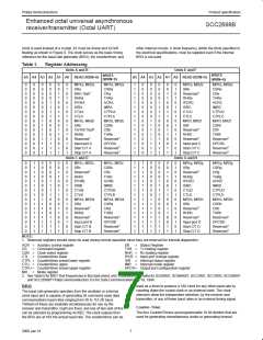
Philips Semiconductors
Product specification
Enhanced octal universal asynchronous
receiver/transmitter (Octal UART)
SCC2698B
receiver indicating that the receiver is ready to receive data. It is
also active low and is, thus, called RTSN. RTSN is on pin MPO. A
receiver’s RTS output will usually be connected to the CTS input of
the associated transmitter. Therefore, one could say that RTS and
CTS are different ends of the same wire!
be sure the TxRDY bit is active immediately before issuing the
transmitter disable instruction. (TxEMT is always set if the transmit-
ter has underrun or has just been enabled), TxRDY sets at the end
of the “start bit” time. It is during the start bit that the data in the
transmit holding register is transferred to the transmit shift register.
MR2(4) is the bit that allows the transmitter to be controlled by the
CTS pin ( MPI0). When this bit is set to one AND the CTS input is
driven high, the transmitter will stop sending data at the end of the
present character being serialized. It is usually the RTS output of
the receiver that will be connected to the transmitter’s CTS input.
The receiver will set RTS high when the receiver FIFO is full AND
the start bit of the fourth character is sensed. Transmission then
stops with four valid characters in the receiver. When MR2(4) is set
to one, CTSN must be at zero for the transmitter to operate. If
MR2(4) is set to zero, the MPI0 pin will have no effect on the opera-
tion of the transmitter.
MULTI-PURPOSE INPUT PIN
The inputs to this unlatched 8-bit port for each block can be read by
the CPU, by performing a read operation as shown in Table 1. A
High input results in a logic one, while a Low input results in a logic
zero. When the input port pins are read on the 84-pin LLCC, they
will appear on the data bus in alternating pairs (i.e., DB0 = MP10a,
DB1 = MPI1a, DB2 = MPI0b, DB3 = MPI1b, DB4 = MPP1a, DB5 =
MPP2a, DB6 = MPP1b, DB7 = MPP2b. Although this example is
shown for input port ‘A’, all ports will have a similar order).
The MPI pin can be programmed as an input to one of several Octal
UART circuits. The function of the pin is selected by programming
the appropriate control register. Change-of-state detectors are
provided for MPI0 and MPI1 for each channel in each block. A
High-to-Low or Low-to-High transition of the inputs lasting longer
than 25 to 50µs sets the MPI change-of-state bit in the interrupt
status register. The bit is cleared via a command. The
MR1(7) is the bit that allows the receiver to control MPO. When
MPO is controlled by the receiver, the meaning of that pin will be
RTS. However, a point of confusion arises in that MPO may also be
controlled by the transmitter. When the transmitter is controlling this
pin, its meaning is not RTS at all. It is, rather, that the transmitter
has finished sending its last data byte. Programming the MPO pin
to be controlled by the receiver and the transmitter at the same time
is allowed, but would usually be incompatible.
change-of-state can be programmed to generate an interrupt to the
CPU by setting the corresponding bit in the interrupt mask register.
The input port pulse detection circuitry uses a 38.4KHz sampling
clock, derived from one of the baud rate generator taps. This
produces a sampling period of slightly more than 25µs (assuming a
3.6864MHz oscillator input). The detection circuitry, in order to
guarantee that a true change in level has occurred, requires two
successive samples be observed at the new logic level. As a
consequence, the minimum duration of the signal change is 25µs if
the transition occurs coincident with the first sample pulse. (The
50µs time refers to the condition where the change-of-state is just
missed and the first change of state is not detected until after an
additional 25µs.)
RTS can also be controlled by the commands 1000 and 1001 in the
command register. RTS is expressed at the MP0 pin which is still an
output port. Therefore, the state of MP0 should be set low (either by
commands of the CR register or by writing to the Output Port Con-
figuration Register) for the receiver to generate the proper RTS sig-
nal. The logic at the output is basically a NAND of the MP0 bit
register and the RTS signal as generated by the receiver. When the
RTS flow control is selected via the MR1(7) bit the state of the MP0
register is not changed. Terminating the use of “Flow Control” (via
the MR registers) will return the MP0 pin to the control of the MP0
register.
Transmitter Disable Note
MULTI-PURPOSE I/O PINS
When the TxEMT bit is set the sequence of instructions: enable
transmitter — load transmit holding register — disable transmitter
will often result in nothing being sent. In the condition of the TxEMT
being set do not issue the disable until the TxRDY bit goes active
again after the character is loaded to the TxFIFO. The data is not
sent if the time between the end of loading the transmit holding reg-
ister and the disable command is less that 3/16 bit time in the 16x
mode. One bit time in the 1x mode.
The multi-purpose pins (MPP) can be programmed as inputs or
outputs using OPCR[7]. When programmed as inputs, the functions
of the pins are selected by programming the appropriate control
registers. When programmed as outputs, the two MPP1 pins (per
block) will provide the transmitter ready (TxRDY) status for each
channel and the MPP2 pins will provide the receiver ready or FIFO
full (RxRDY/FFULL) status for each channel.
This is sometimes the condition when the RS485 automatic “turn-
around” is enabled . It will also occur when only one character is to
be sent and it is desired to disable the transmitter immediately after
the character is loaded.
MULTI-PURPOSE OUTPUT PIN
This pin can be programmed to serve as a request-to-send output,
the counter/timer output, the output for the 1X or 16X transmitter or
receiver clocks, the TxRDY output or the RxRDY/FFULL output (see
OPCR [2:0] and OPCR [6:4] – MPO Output Select).
In general, when it is desired to disable the transmitter before the
last character is sent AND the TxEMT bit is set in the status register
11
2000 Jan 31

 NXP [ NXP ]