Philips Semiconductors
Product specification
Enhanced octal universal asynchronous
receiver/transmitter (Octal UART)
SCC2698B
MR2[7:6] – Mode Select
REGISTERS
The Octal UART can operate in one of four modes. MR2[7:6] = 00 is
the normal mode, with the transmitter and receiver operating
independently. MR2[7:6] = 01 places the channel in the automatic
echo mode, which automatically re-transmits the received data. The
following conditions are true while in automatic echo mode:
1. Received data is re-clocked and retransmitted on the TxD output.
2. The receive clock is used for the transmitter.
The operation of the Octal UART is programmed by writing control
words into the appropriate registers. Operational feedback is
provided via status registers which can be read by the CPU.
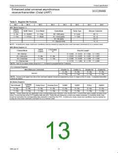
Addressing of the registers is described in Table 1.
The bit formats of the Octal UART registers are depicted in Table 2.
These are shown for block A. The bit format for the other blocks is
the same.
3. The receiver must be enabled, but the transmitter need not be
enabled.
MR1 – Mode Register 1
4. The TxRDY and TxEMT status bits are inactive.
5. The received parity is checked, but is not regenerated for
transmission, i.e., transmitted parity bit is as received.
6. Characterframing is checked, but the stop bits are retransmitted as
received.
7. A received break is echoed as received until the next valid start bit
is detected.
8. CPU-to-receiver communication continues normally, but the
CPU-to-transmitter link is disabled.
MR1 is accessed when the MR pointer points to MR1. The pointer is
set to MR1 by RESET or by a set pointer command applied via the
CR. After reading or writing MR1, the pointers are set at MR2.
MR1[7] – Receiver Request-to-Send Control
This bit controls the deactivation of the RTSN output (MPO) by the
receiver. This output is manually asserted and negated by
commands applied via the command register. MR1[7] = 1 causes
RTSN to be automatically negated upon receipt of a valid start bit if
the receiver FIFO is full. RTSN is reasserted when an empty FIFO
position is available. This feature can be used to prevent overrun in
the receiver by using the RTSN output signal to control the CTS
input of the transmitting device.
Two diagnostic modes can also be selected. MR2[7:6] = 10 selects
local loopback mode. In this mode:
1. The transmitter output is internally connected to the receiver
input.
2. The transmit clock is used for the receiver.
3. The TxD output is held high.
4. The RxD input is ignored.
5. The transmitter must be enabled, but the receiver need not be
enabled.
MR1[6] – Receiver Interrupt Select
This bit selects either the receiver ready status (RxRDY) or the FIFO
full status (FFULL) to be used for CPU interrupts.
MR1[5] – Error Mode Select
6. CPU to transmitter and receiver communications continue
normally.
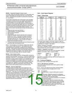
This bit selects the operating mode of the three FIFOed status bits
(FE, PE, received break). In the character mode, status is provided
on a character-by-character basis; the status applies only to the
character at the top of the FIFO. In the block mode, the status
provided in the SR for these bits is the accumulation (logical-OR) of
the status for all characters coming to the top of the FIFO since the
last reset error command was issued.
The second diagnostic mode is the remote loopback mode, selected
by MR2[7:6] = 11. In this mode:
1. Received data is re-clocked and retransmitted on the TXD
output.
2. The receive clock is used for the transmitter.
3. Received data is not sent to the local CPU, and the error status
conditions are inactive.
4. The received parity is not checked and is not regenerated for
transmission, i.e., the transmitted parity bit is as received.
5. The receiver must be enabled, but the transmitter need not be
enabled.
MR1[4:3] – Parity Mode Select
If ‘with parity’ or ‘force parity’ is selected, a parity bit is added to the
transmitted character and the receiver performs a parity check on
incoming data. MR1[4:3] = 11 selects the channel to operate in the
special wake-up mode.
MR1[2] – Parity Type Select
6. Character framing is not checked, and the stop bits are
retransmitted as received.
7. A received break is echoed as received until the next valid start
bit is detected.
This bit selects the parity type (odd or even) if the ‘with parity’ mode
is programmed by MR1[4:3], and the polarity of the forced parity bit
if the ‘force parity’ mode is programmed. It has no effect if the ‘no
parity’ mode is programmed. In the special ‘wake-up’ mode, it
selects the polarity of the transmitted A/D bit.
The user must exercise care when switching into and out of the
various modes. The selected mode will be activated immediately
upon mode selection, even if this occurs in the middle of a received
or transmitted character. Likewise, if a mode is deselected, the
device will switch out of the mode immediately. An exception to this
is switching out of autoecho or remote loopback modes; if the
deselection occurs just after the receiver has sampled the stop bit
(indicated in autoecho by assertion of RxRDY), and the transmitter
is enabled, the transmitter will remain in autoecho mode until the
entire stop bit has been retransmitted.
MR1[1:0] – Bits Per Character Select
This field selects the number of data bits per character to be
transmitted and received. The character length does not include the
start, parity, and stop bits.
MR2 – Mode Register 2
MR2 is accessed when the channel MR pointer points to MR2,
which occurs after any access to MR1. Accesses to MR2 do not
change the pointer.
12
2000 Jan 31

 NXP [ NXP ]