Philips Semiconductors
Product specification
Dual asynchronous receiver/transmitter (DUART)
SCC2692
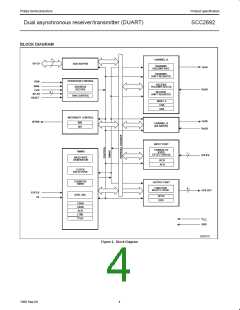
BLOCK DIAGRAM
• In the timer mode it generates a square wave.
• In the counter mode it generates a time delay.
The SCC2692 DUART consists of the following eight major sections:
data bus buffer, operation control, interrupt control, timing,
communications Channels A and B, input port and output port. Refer
to the Block Diagram.
• In the time out mode it monitors the receiver data flow and signals
data flow has paused. In the time out mode the receiver controls
the starting/stopping of the C/T.
Data Bus Buffer
The data bus buffer provides the interface between the external and
internal data buses. It is controlled by the operation control block to
allow read and write operations to take place between the controlling
CPU and the DUART.
The counter operates as a down counter and sets its output bit in
the ISR (Interrupt Status Register) each time it passes through 0.
The output of the counter/timer may be seen on one of the OP pins
or as an Rx or Tx clock.
The Timer/Counter is controlled with six (6) “commands”; Start C/T,
Stop C/T, write C/T, preset registers, read C/T value, set or reset
time out mode.
Operation Control
The operation control logic receives operation commands from the
CPU and generates appropriate signals to internal sections to
control device operation. It contains address decoding and read and
write circuits to permit communications with the microprocessor via
the data bus buffer.
Please see the detail of the commands under the Counter/Timer
register descriptions.
Communications Channels A and B
Interrupt Control
Each communications channel of the SCC2692 comprises a
full-duplex asynchronous receiver/transmitter (UART). The operating
frequency for each receiver and transmitter can be selected
independently from the baud rate generator, the counter/timer, or
from an external input.
A single active-Low interrupt output (INTRN) is provided which is
activated upon the occurrence of any of eight internal events.
Associated with the interrupt system are the Interrupt Mask Register
(IMR) and the Interrupt Status Register (ISR). The IMR can be
programmed to select only certain conditions to cause INTRN to be
asserted. The ISR can be read by the CPU to determine all currently
active interrupting conditions.
The transmitter accepts parallel data from the CPU, converts it to a
serial bit stream, inserts the appropriate start, stop, and optional
parity bits and outputs a composite serial stream of data on the TxD
output pin. The receiver accepts serial data on the RxD pin,
converts this serial input to parallel format, checks for start bit, stop
bit, parity bit (if any), or break condition and sends an assembled
character to the CPU.
Outputs OP3-OP7 can be programmed to provide discrete interrupt
outputs for the transmitter, receivers, and counter/timer.
TIMING CIRCUITS
Input Port
Crystal Clock
The inputs to this unlatched 7-bit port can be read by the CPU by
performing a read operation at address H’D’. A High input results in
a logic 1 while a Low input results in a logic 0. D7 will always read
as a logic 1. The pins of this port can also serve as auxiliary inputs
to certain portions of the DUART logic.
The timing block consists of a crystal oscillator, a baud rate
generator, a programmable 16-bit counter/timer, and four clock
selectors. The crystal oscillator operates directly from a crystal
connected across the X1/CLK and X2 inputs. If an external clock of
the appropriate frequency is available, it may be connected to
X1/CLK. The clock serves as the basic timing reference for the Baud
Rate Generator (BRG), the counter/timer, and other internal circuits.
A clock signal within the limits specified in the specifications section
of this data sheet must always be supplied to the DUART.
Four change-of-state detectors are provided which are associated
with inputs IP3, IP2, IP1 and IP0. A High-to-Low or Low-to-High
transition of these inputs, lasting longer than 25 - 50µs, will set the
corresponding bit in the input port change register. The bits are
cleared when the register is read by the CPU. Any change-of-state
can also be programmed to generate an interrupt to the CPU.
If an external clock is used instead of a crystal, X1 should be driven
using a configuration similar to the one in Figure 7.
The input port pulse detection circuitry uses a 38.4KHz sampling
clock derived from one of the baud rate generator taps. This results
in a sampling period of slightly more than 25µs (this assumes that
the clock input is 3.6864MHz). The detection circuitry, in order to
guarantee that a true change in level has occurred, requires two
successive samples at the new logic level be observed. As a
consequence, the minimum duration of the signal change is 25µs if
the transition occurs “coincident with the first sample pulse”. The
50µs time refers to the situation in which the change-of-state is “just
missed” and the first change-of-state is not detected until 25µs later.
All the IP pins have a small pull-up device that will source 1 to 4 mA
BRG
The baud rate generator operates from the oscillator or external
clock input and is capable of generating 23 commonly used data
communications baud rates ranging from 50 to 130.4K baud. A
3.6864MHz crystal or external clock must be used to get the
standard baud rate. The clock outputs from the BRG are at 16X the
actual baud rate. The counter/timer can be used as a timer to
produce a 16X clock for any other baud rate by counting down the
crystal clock or an external clock. The four clock selectors allow the
independent selection, for each receiver and transmitter, of any of
these baud rates or external timing signal.
of current from V . These pins do not require pull-up devices or
CC
V
CC
connections if they are not used.
Counter/Timer (C/T)
Output Port
The counter timer is a 16 bit programmable divider that operates
one of three modes: Counter, Timer or Time Out mode. In all three
modes it uses the 16-bit value loaded to the CTUR and CTLR
registers. (Counter timer upper and lower preset registers).
The output port pins may be controlled by the OPR, OPCR, MR and
CR registers. Via appropriate programming they may be just another
parallel port to external circuits, or they may represent many internal
8
1998 Sep 04

 NXP [ NXP ]