Philips Semiconductors
Product specification
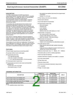
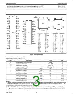
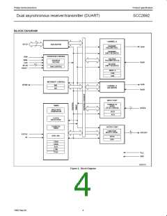
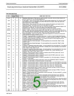
Dual asynchronous receiver/transmitter (DUART)
SCC2692
1, 2, 3
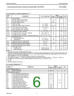
DC ELECTRICAL CHARACTERISTICS
LIMITS
Typ
SYM-
BOL
PARAMETER
TEST CONDITIONS
UNIT
Max
Min
V
V
V
V
Input low voltage
0.8
V
V
V
V
IL
6
Input high voltage (except X1/CLK)
Input high voltage (except X1/CLK)
Input high voltage (X1/CLK)
2.0
2.5
IH
IH
IH
7
0.8 V
CC
V
V
Output low voltage
0.4
V
V
I
= 2.4mA
OL
OL
4
Output high voltage (except OD outputs)
V
CC
-0.5
I
= -400µA
OH
OH
I
X1/CLK input current - power down
X1/CLK input low current - operating
X1/CLK input high current - operating
-10
+10
0
75
µA
µA
µA
V
= 0 to V
IX1PD
IN
CC
I
I
V
IN
= 0
-75
0
ILX1
V
= V
IHX1
IN
CC
I
I
I
I
X2 output high current - operating
0
+75
-1
0
µA
mA
µA
V
V
= V , X1 = 0
CC
OHX2
OUT
X2 output high short circuit current - operating
X2 output low current - operating
X2 output low short circuit current - operating and power down
V
= 0, X1 = 0
-10
-75
1
OHX2S
OLX2
OUT
= 0, X1 = V
OUT
CC
V
OUT
= V , X1 = V
CC
10
mA
OLX2S
CC
Input leakage current:
All except input port pins
Input port pins
I
V
V
= 0 to V
= 0 to V
-10
-20
+10
+10
µA
µA
I
IN
IN
V
CC
CC
I
I
Output off current high, 3-state data bus
Output off current low, 3-state data bus
= V
CC
10
µA
µA
OZH
IN
V
IN
= 0V
-10
-10
OZL
I
I
Open-drain output low current in off-state
Open-drain output high current in off-state
V
IN
= 0
µA
µA
ODL
V
= V
CC
10
ODH
IN
5
Power supply current
I
Operating mode
Power down mode
CMOS input levels
CMOS input levels
10
10
mA
CC
8
2
mA
NOTES:
1. Parameters are valid over specified temperature range.
2. All voltage measurements are referenced to ground (GND). For testing, all inputs swing between 0.4V and 2.4V with a transition time of 5ns
maximum. For X1/CLK this swing is between 0.4V and 4.4V. All time measurements are referenced at input voltages of 0.8V and 2.0V and
output voltages of 0.8V and 2.0V, as appropriate.
3. Typical values are at +25°C, typical supply voltages, and typical processing parameters.
4. Test conditions for outputs: C = 150pF, except interrupt outputs. Test conditions for interrupt outputs: C = 50pF, R = 2.7KΩ to V
.
L
L
L
CC
5. All outputs are disconnected. Inputs are switching between CMOS levels of V -0.2V and V + 0.2V.
CC
SS
6. T > 0°C
A
7. T < 0°C
A
8. See UART application note for 5µA.
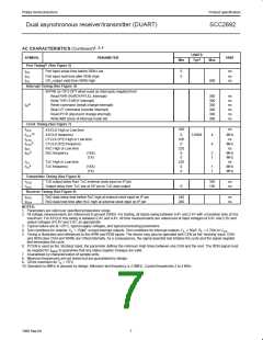
1, 2, 4
AC CHARACTERISTICS
LIMITS
SYMBOL
PARAMETER
UNIT
3
Min
Typ
Max
Reset Timing (See Figure 3)
t
RESET pulse width
200
ns
RES
5
Bus Timing (See Figure 4)
t
t
t
t
t
t
t
t
t
t
t
t
A0-A3 setup time to RDN, WRN Low
A0-A3 hold time from RDN, WRN Low
CEN setup time to RDN, WRN Low
CEN hold time from RDN, WRN High
WRN, RDN pulse width
10
100
0
0
225
ns
ns
ns
ns
ns
ns
ns
ns
ns
ns
ns
ns
AS
AH
CS
CH
RW
DD
DA
DF
DI
Data valid after RDN Low
RDN Low to data bus active
175
125
7
15
Data bus floating after RDN High
7
RDN High to data bus invalid
20
100
20
Data setup time before WRN High
Data hold time after WRN High
High time between reads and/or writes
DS
DH
RWD
5, 6
200
6
1998 Sep 04

 NXP [ NXP ]