Philips Semiconductors
Product specification
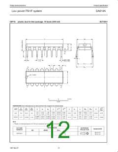
Low power FM IF system
SA614A
42k
9
11
12
V+
40k
BPF
8
BPF
10
40k
80k
SR00329
SR00330
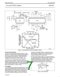
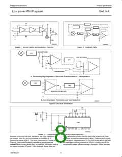
Figure 7. Second Limiter and Quadrature Detector
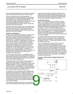
Figure 8. Feedback Paths
HIGH IMPEDANCE
BPF
HIGH IMPEDANCE
BPF
LOW IMPEDANCE
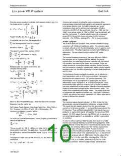
a. Terminating High Impedance Filters with Transformation to Low Impedance
BPF
BPF
A
RESISTIVE LOSS INTO BPF
b. Low Impedance Termination and Gain Reduction
Figure 9. Practical Termination
SR00331
430
11
16
15
14
13
12
10
9
8
614A
430
1
2
3
4
5
6
7
SR00332
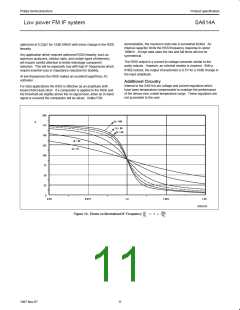
Figure 10. Crystal Input Filter with Ceramic Interstage Filter
Because of the very high gain, bandwidth and input impedance of
the limiters, there is a very real potential for instability at IF
frequencies above 455kHz. The basic phenomenon is shown in
Figure 8. Distributed feedback (capacitance, inductance and
radiated fields) forms a divider from the output of the limiters back to
the inputs (including RF input). If this feedback divider does not
cause attenuation greater than the gain of the forward path, then
oscillation or low level regeneration is likely. If regeneration occurs,
two symptoms may be present: (1)The RSSI output will be high with
no signal input (should nominally be 250mV or lower), and (2) the
demodulated output will demonstrate a threshold. Above a certain
8
1997 Nov 07

 NXP [ NXP ]