Philips Semiconductors
Product specification
Low power FM IF system
SA614A
0.5
to
SFG455A3
1.3µH
22pF
1nF
0.1µF
NE604A TEST CIRCUIT
0.1µF
455kHz
Q=20
44.545
3rd OVERTURE
XTAL
5.5µH
5.6pF
0.1µF
SFG455A3
10pF
+6V
16
15
14
13
12
11
10
9
8
8
1
7
6
5
4
100nF
10nF
6.8µF
0.1µF
SA604A
SA602
2
0.1µF
3
1
2
3
4
5
6
7
47pF
22pF
0.1µF
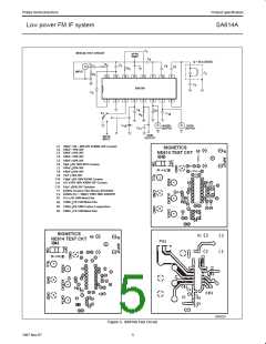
DATA
OUT
0.21
100k
to
0.28µH
+6V
C–MSG
FILTER
AUDIO
OUT
MUTE
100nF
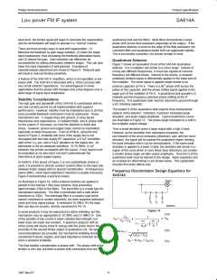
RSSI
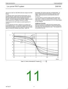
614A IF INPUT (µV) (1500Ω)
10
100
1k
10k
100k
AUDIO
–0
4V
3V
2V
1V
RSSI (VOLTS)
–20
–40
–60
THD + NOISE
AM (80% MOD)
NOISE
–80
–120
–100
–80
–60
–40
–20
602 RF INPUT (dBm) (50Ω)
SR00327
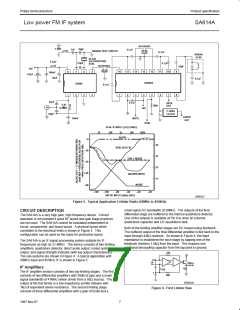
Figure 5. Typical Application Cellular Radio (45MHz to 455kHz)
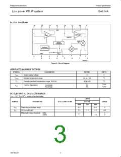
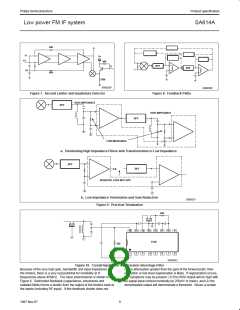
small signal AC bandwidth of 28MHz. The outputs of the final
differential stage are buffered to the internal quadrature detector.
One of the outputs is available at Pin 9 to drive an external
quadrature capacitor and L/C quadrature tank.
CIRCUIT DESCRIPTION
The SA614A is a very high gain, high frequency device. Correct
operation is not possible if good RF layout and gain stage practices
are not used. The SA614A cannot be evaluated independent of
circuit, components, and board layout. A physical layout which
correlates to the electrical limits is shown in Figure 3. This
configuration can be used as the basis for production layout.
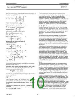
Both of the limiting amplifier stages are DC biased using feedback.
The buffered output of the final differential amplifier is fed back to the
input through 42kΩ resistors. As shown in Figure 4, the input
impedance is established for each stage by tapping one of the
feedback resistors 1.6kΩ from the input. This requires one
additional decoupling capacitor from the tap point to ground.
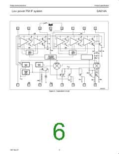
The SA614A is an IF signal processing system suitable for IF
frequencies as high as 21.4MHz. The device consists of two limiting
amplifiers, quadrature detector, direct audio output, muted audio
output, and signal strength indicator (with log output characteristic).
The sub-systems are shown in Figure 4. A typical application with
45MHz input and 455kHz IF is shown in Figure 5.
42k
V+
15
16
700
14
IF Amplifiers
7k
1.6k
The IF amplifier section consists of two log-limiting stages. The first
consists of two differential amplifiers with 39dB of gain and a small
signal bandwidth of 41MHz (when driven from a 50Ω source). The
output of the first limiter is a low impedance emitter follower with
1kΩ of equivalent series resistance. The second limiting stage
consists of three differential amplifiers with a gain of 62dB and a
1
40k
SR00328
Figure 6. First Limiter Bias
7
1997 Nov 07

 NXP [ NXP ]