Philips Semiconductors
Product specification
Low power FM IF system
SA614A
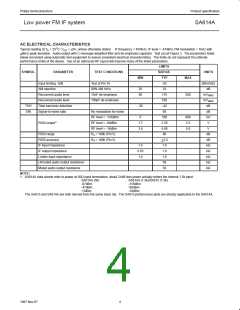
AC ELECTRICAL CHARACTERISTICS
Typical reading at T = 25°C; V = +6V, unless otherwise stated. IF frequency = 455kHz; IF level = -47dBm; FM modulation = 1kHz with
A
CC
+8kHz peak deviation. Audio output with C-message weighted filter and de-emphasis capacitor. Test circuit Figure 3. The parameters listed
below are tested using automatic test equipment to assure consistent electrical characterristics. The limits do not represent the ultimate
performance limits of the device. Use of an optimized RF layout will improve many of the listed parameters.
LIMITS
SYMBOL
PARAMETER
TEST CONDITIONS
SA614A
TYP
-92
UNITS
MIN
MAX
Input limiting -3dB
Test at Pin 16
dBm/50Ω
AM rejection
80% AM 1kHz
25
60
33
dB
Recovered audio level
Recovered audio level
Total harmonic distortion
Signal-to-noise ratio
15nF de-emphasis
150pF de-emphasis
175
530
-42
260
mV
mV
RMS
RMS
THD
S/N
-30
dB
No modulation for noise
RF level = -118dBm
RF level = -68dBm
RF level = -18dBm
68
dB
mV
V
0
160
2.50
4.80
80
800
3.3
5.8
1
RSSI output
1.7
3.6
V
RSSI range
R = 100k (Pin 5)
4
dB
dB
kΩ
kΩ
kΩ
kΩ
kΩ
RSSI accuracy
R = 100k (Pin 5)
4
+2.0
1.6
IF input impedance
1.4
0.85
1.4
IF output impedance
Limiter input impedance
Unmuted audio output resistance
Muted audio output resistance
1.0
1.6
58
58
NOTE:
1. SA614A data sheets refer to power at 50Ω input termination; about 21dB less power actually enters the internal 1.5k input.
SA614A (50)
-97dBm
-47dBm
SA614A (1.5k)/SA615 (1.5k)
-118dBm
-68dBm
-18dBm
+3dBm
The SA615 and SA614A are both derived from the same basic die. The SA615 performance plots are directly applicable to the SA614A.
4
1997 Nov 07

 NXP [ NXP ]