Philips Semiconductors
Product specification
Low power FM IF system
SA614A
input level, the limited signal will begin to dominate the regeneration,
and the demodulator will begin to operate in a “normal” manner.
quadrature tank and the filters. Most filters demonstrate a large
phase shift across their passband (especially at the edges). If the
quadrature detector is tuned to the edge of the filter passband, the
combined filter and quadrature phase shift can aggravate stability.
This is not usually a problem, but should be kept in mind.
There are three primary ways to deal with regeneration: (1)
Minimize the feedback by gain stage isolation, (2) lower the stage
input impedances, thus increasing the feedback attenuation factor,
and (3) reduce the gain. Gain reduction can effectively be
accomplished by adding attenuation between stages. This can also
lower the input impedance if well planned. Examples of
impedance/gain adjustment are shown in Figure 9. Reduced gain
will result in reduced limiting sensitivity.
Quadrature Detector
Figure 7 shows an equivalent circuit of the SA614A quadrature
detector. It is a multiplier cell similar to a mixer stage. Instead of
mixing two different frequencies, it mixes two signals of common
frequency but different phase. Internal to the device, a constant
amplitude (limited) signal is differentially applied to the lower port of
the multiplier. The same signal is applied single-ended to an
A feature of the SA614A IF amplifiers, which is not specified, is low
phase shift. The SA614A is fabricated with a 10GHz process with
very small collector capacitance. It is advantageous in some
applications that the phase shift changes only a few degrees over a
wide range of signal input amplitudes.
external capacitor at Pin 9. There is a 90° phase shift across the
plates of this capacitor, with the phase shifted signal applied to the
upper port of the multiplier at Pin 8. A quadrature tank (parallel L/C
network) permits frequency selective phase shifting at the IF
frequency. This quadrature tank must be returned to ground through
a DC blocking capacitor.
Stability Considerations
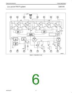
The high gain and bandwidth of the SA614A in combination with its
very low currents permit circuit implementation with superior
performance. However, stability must be maintained and, to do that,
every possible feedback mechanism must be addressed. These
mechanisms are: 1) Supply lines and ground, 2) stray layout
inductances and capacitances, 3) radiated fields, and 4) phase shift.
As the system IF increases, so must the attention to fields and
strays. However, ground and supply loops cannot be overlooked,
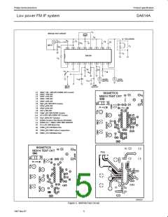
especially at lower frequencies. Even at 455kHz, using the test
layout in Figure 3, instability will occur if the supply line is not
decoupled with two high quality RF capacitors, a 0.1µF monolithic
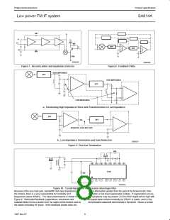
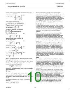
The loaded Q of the quadrature tank impacts three fundamental
aspects of the detector: Distortion, maximum modulated peak
deviation, and audio output amplitude. Typical quadrature curves
are illustrated in Figure 12. The phase angle translates to a shift in
the multiplier output voltage.
Thus a small deviation gives a large output with a high Q tank.
However, as the deviation from resonance increases, the
non-linearity of the curve increases (distortion), and, with too much
deviation, the signal will be outside the quadrature region (limiting
the peak deviation which can be demodulated). If the same peak
deviation is applied to a lower Q tank, the deviation will remain in a
region of the curve which is more linear (less distortion), but creates
a smaller phase angle (smaller output amplitude). Thus the Q of the
quadrature tank must be tailored to the design. Basic equations and
an example for determining Q are shown below. This explanation
includes first-order effects only.
right at the V pin, and a 6.8µF tantalum on the supply line. An
CC
electrolytic is not an adequate substitute. At 10.7MHz, a 1µF
tantalum has proven acceptable with this layout. Every layout must
be evaluated on its own merit, but don’t underestimate the
importance of good supply bypass.
At 455kHz, if the layout of Figure 3 or one substantially similar is
used, it is possible to directly connect ceramic filters to the input and
between limiter stages with no special consideration. At frequencies
above 2MHz, some input impedance reduction is usually necessary.
Figure 9 demonstrates a practical means.
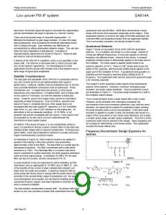
Frequency Discriminator Design Equations for
SA614A
V
OUT
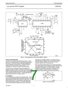
As illustrated in Figure 10, 430Ω external resistors are applied in
parallel to the internal 1.6kΩ load resistors, thus presenting
approximately 330Ω to the filters. The input filter is a crystal type for
narrowband selectivity. The filter is terminated with a tank which
transforms to 330Ω. The interstage filter is a ceramic type which
doesn’t contribute to system selectivity, but does suppress wideband
noise and stray signal pickup. In wideband 10.7MHz IFs the input
filter can also be ceramic, directly connected to Pin 16.
SR00333
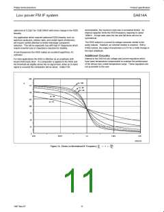
Figure 11.
In some products it may be impractical to utilize shielding, but this
mechanism may be appropriate to 10.7MHz and 21.4MHz IF. One
of the benefits of low current is lower radiated field strength, but
lower does not mean non-existent. A spectrum analyzer with an
active probe will clearly show IF energy with the probe held in the
proximity of the second limiter output or quadrature coil. No specific
recommendations are provided, but mechanical shielding should be
considered if layout, bypass, and input impedance reduction do not
solve a stubborn instability.
(1a)
C
S
1
+
V
IN
V
O
=
C
+ C
S
ω
ω
1
2
P
1
1 +
1
( )
Q S
S
1
(1b)
(1c)
where ω =
1
L(C + C )
P
S
Q = R (C + C ) ω
1
1
P
S
The final stability consideration is phase shift. The phase shift of the
limiters is very low, but there is phase shift contribution from the
9
1997 Nov 07

 NXP [ NXP ]