PCA9675
NXP Semiconductors
Remote 16-bit I/O expander for Fm+ I2C-bus with interrupt
10. Application design-in information
10.1 Bidirectional I/O expander applications
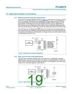
In the 8-bit I/O expander application shown in Figure 22, P00 and P01 are inputs, and P02
to P07 are outputs. When used in this configuration, during a write, the input (P00 and
P01) must be written as HIGH so the external devices fully control the input ports. The
desired HIGH or LOW logic levels may be written to the I/Os used as outputs (P02 to
P07). During a read, the logic levels of the external devices driving the input ports (P00
and P01) and the previous written logic level to the output ports (P02 to P07) will be read.
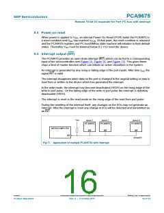
The GPIO also has an interrupt line (INT) that can be connected to the interrupt logic of
the microprocessor. By sending an interrupt signal on this line, the remote I/O informs the
microprocessor that there is incoming data or a change of data on its ports without having
to communicate via the I2C-bus.
V
DD
V
DD
V
DD
SDA
SCL
INT
P00
P01
P02
P03
P04
P05
P06
P07
temperature sensor
battery status
CORE
PROCESSOR
control for latch
control for switch
control for audio
control for camera
control for MP3
AD0
AD1
AD2
002aab812
Fig 22. Bidirectional I/O expander application
10.2 High current-drive load applications
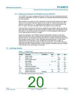
The GPIO has a maximum sinking current of 25 mA per bit. In applications requiring
additional drive, two port pins in the same octal may be connected together to sink up to
50 mA current. Both bits must then always be turned on or off together. Up to 8 pins (one
octal) can be connected together to drive 200 mA.
V
DD
V
V
DD
DD
SDA
SCL
INT
P00
P01
P02
P03
P04
P05
P06
P07
CORE
PROCESSOR
LOAD
AD0
AD1
AD2
002aab813
Fig 23. High current-drive load application
PCA9675
All information provided in this document is subject to legal disclaimers.
© NXP B.V. 2011. All rights reserved.
Product data sheet
Rev. 2 — 3 October 2011
19 of 34

 NXP [ NXP ]