Philips Semiconductors
Preliminary data
Low power, low price, low pin count (20 pin)
microcontroller with 4 kbyte OTP
87LPC764
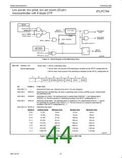
500 kHz
R/C OSCILLATOR
CLOCK OUT
WDS2–0
(WDCON.2–0)
ENABLE
8 TO 1 MUX
8 MSBs
WATCHDOG
RESET
WDCLK * WDTE
STATE CLOCK
WATCHDOG
INTERRUPT
20-BIT COUNTER
CLEAR
WDTE + WDRUN
WDTE (UCFG1.7)
WATCHDOG
FEED DETECT
S
R
WDOVF
(WDCON.5)
Q
BOD (xxx.x)
POR (xxx.x)
SU01182
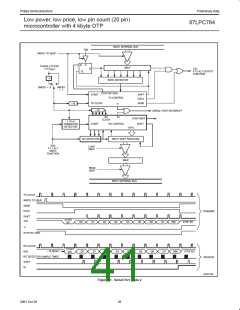
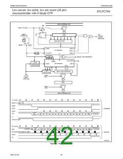
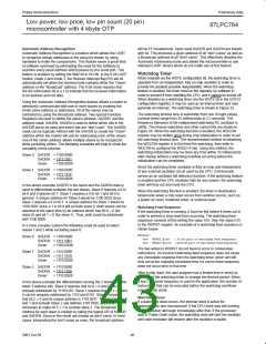
Figure 33. Block Diagram of the Watchdog Timer
WDCON Address: A7h
Reset Value: S 30h for a watchdog reset.
S 10h for other rest sources if the watchdog is enabled via the WDTE configuration bit.
S 00h for other reset sources if the watchdog is disabled via the WDTE configuration bit.
Not Bit Addressable
7
6
5
4
3
2
1
0
—
—
WDOVF WDRUN WDCLK WDS2
WDS1
WDS0
BIT
SYMBOL
—
FUNCTION
WDCON.7, 6
WDCON.5
Reserved for future use. Should not be set to 1 by user programs.
WDOVF
Watchdog timer overflow flag. Set when a watchdog reset or timer overflow occurs. Cleared when
the watchdog is fed.
WDCON.4
WDCON.3
WDRUN
WDCLK
Watchdog run control. The watchdog timer is started when WDRUN = 1 and stopped when
WDRUN = 0. This bit is forced to 1 (watchdog running) if the WDTE configuration bit = 1.
Watchdog clock select. The watchdog timer is clocked by CPU clock/6 when WDCLK = 1 and by
the watchdog RC oscillator when WDCLK = 0. This bit is forced to 0 (using the watchdog RC
oscillator) if the WDTE configuration bit = 1.
WDCON.2–0 WDS2–0
Watchdog rate select.
WDS2–0
0 0 0
0 0 1
0 1 0
0 1 1
1 0 0
1 0 1
1 1 0
1 1 1
Timeout Clocks
8,192
Minimum Time
10 ms
Nominal Time
25 ms
Maximum Time
40 ms
16,384
20 ms
50 ms
80 ms
32,768
41 ms
100 ms
200 ms
400 ms
800 ms
1.60 sec
3.20 sec
160 ms
65,536
82 ms
320 ms
131,072
262,144
524,288
1,048,576
165 ms
330 ms
660 ms
1.3 sec
640 ms
1280 ms
2.60 sec
5.30 sec
SU01476
Figure 34. Watchdog Timer Control Register (WDCON)
41
2001 Oct 26

 NXP [ NXP ]