Philips Semiconductors
Preliminary data
Low power, low price, low pin count (20 pin)
microcontroller with 4 kbyte OTP
87LPC764
Automatic Address Recognition
will be FF hexadecimal. Upon reset SADDR and SADEN are loaded
with 0s. This produces a given address of all “don’t cares” as well as
a Broadcast address of all “don’t cares”. This effectively disables the
Automatic Addressing mode and allows the microcontroller to use
standard UART drivers which do not make use of this feature.
Automatic Address Recognition is a feature which allows the UART
to recognize certain addresses in the serial bit stream by using
hardware to make the comparisons. This feature saves a great deal
of software overhead by eliminating the need for the software to
examine every serial address which passes by the serial port. This
feature is enabled by setting the SM2 bit in SCON. In the 9 bit UART
modes, mode 2 and mode 3, the Receive Interrupt flag (RI) will be
automatically set when the received byte contains either the “Given”
address or the “Broadcast” address. The 9 bit mode requires that
the 9th information bit is a 1 to indicate that the received information
is an address and not data.
Watchdog Timer
When enabled via the WDTE configuration bit, the watchdog timer is
operated from an independent, fully on-chip oscillator in order to
provide the greatest possible dependability. When the watchdog
feature is enabled, the timer must be fed regularly by software in
order to prevent it from resetting the CPU, and it cannot be turned off.
When disabled as a watchdog timer (via the WDTE bit in the UCFG1
configuration register), it may be used as an interval timer and may
generate an interrupt. The watchdog timer is shown in Figure 33.
Using the Automatic Address Recognition feature allows a master to
selectively communicate with one or more slaves by invoking the
Given slave address or addresses. All of the slaves may be
contacted by using the Broadcast address. Two special Function
Registers are used to define the slave’s address, SADDR, and the
address mask, SADEN. SADEN is used to define which bits in the
SADDR are to be used and which bits are “don’t care”. The SADEN
mask can be logically ANDed with the SADDR to create the “Given”
address which the master will use for addressing each of the slaves.
Use of the Given address allows multiple slaves to be recognized
while excluding others. The following examples will help to show the
versatility of this scheme:
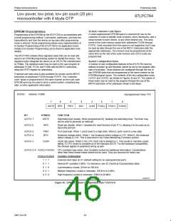
The watchdog timeout time is selectable from one of eight values,
nominal times range from 25 milliseconds to 3.2 seconds. The
frequency tolerance of the independent watchdog RC oscillator is
±60%. The timeout selections and other control bits are shown in
Figure 34. When the watchdog function is enabled, the WDCON
register may be written once during chip initialization in order to set
the watchdog timeout time. The recommended method of initializing
the WDCON register is to first feed the watchdog, then write to
WDCON to configure the WDS2–0 bits. Using this method, the
watchdog initialization may be done any time within 10 milliseconds
after startup without a watchdog overflow occurring before the
initialization can be completed.
Slave 0 SADDR = 1100 0000
SADEN = 1111 1101
Given
= 1100 00X0
Since the watchdog timer oscillator is fully on-chip and independent
of any external oscillator circuit used by the CPU, it intrinsically
serves as an oscillator fail detection function. If the watchdog feature
is enabled and the CPU oscillator fails for any reason, the watchdog
timer will time out and reset the CPU.
Slave 1 SADDR = 1100 0000
SADEN = 1111 1110
Given
= 1100 000X
In the above example SADDR is the same and the SADEN data is
used to differentiate between the two slaves. Slave 0 requires a 0 in
bit 0 and it ignores bit 1. Slave 1 requires a 0 in bit 1 and bit 0 is
ignored. A unique address for Slave 0 would be 1100 0010 since
slave 1 requires a 0 in bit 1. A unique address for slave 1 would be
1100 0001 since a 1 in bit 0 will exclude slave 0. Both slaves can be
selected at the same time by an address which has bit 0 = 0 (for
slave 0) and bit 1 = 0 (for slave 1). Thus, both could be addressed
with 1100 0000.
When the watchdog function is enabled, the timer is deactivated
temporarily when a chip reset occurs from another source, such as
a power on reset, brownout reset, or external reset.
Watchdog Feed Sequence
If the watchdog timer is running, it must be fed before it times out in
order to prevent a chip reset from occurring. The watchdog feed
sequence consists of first writing the value 1Eh, then the value E1h
to the WDRST register. An example of a watchdog feed sequence is
shown below.
In a more complex system the following could be used to select
slaves 1 and 2 while excluding slave 0:
WDFeed:
Slave 0 SADDR = 1100 0000
SADEN = 1111 1001
mov WDRST,#1eh ;Firstpartofwatchdogfeedsequence.
mov WDRST,#0e1h ;Secondpartofwatchdogfeedsequence.
Given
= 1100 0XX0
The two writes to WDRST do not have to occur in consecutive
instructions. An incorrect watchdog feed sequence does not cause
any immediate response from the watchdog timer, which will still
time out at the originally scheduled time if a correct feed sequence
does not occur prior to that time.
Slave 1 SADDR = 1110 0000
SADEN = 1111 1010
Given
= 1110 0X0X
Slave 2 SADDR = 1110 0000
SADEN = 1111 1100
After a chip reset, the user program has a limited time in which to
either feed the watchdog timer or change the timeout period. When
a low CPU clock frequency is used in the application, the number of
instructions that can be executed before the watchdog overflows
may be quite small.
Given
= 1110 00XX
In the above example the differentiation among the 3 slaves is in the
lower 3 address bits. Slave 0 requires that bit 0 = 0 and it can be
uniquely addressed by 1110 0110. Slave 1 requires that bit 1 = 0 and
it can be uniquely addressed by 1110 and 0101. Slave 2 requires
that bit 2 = 0 and its unique address is 1110 0011. To select Slaves 0
and 1 and exclude Slave 2 use address 1110 0100, since it is
necessary to make bit 2 = 1 to exclude slave 2. The Broadcast
Address for each slave is created by taking the logical OR of SADDR
and SADEN. Zeros in this result are treated as don’t-cares. In most
cases, interpreting the don’t-cares as ones, the broadcast address
Watchdog Reset
If a watchdog reset occurs, the internal reset is active for
approximately one microsecond. If the CPU clock was still running,
code execution will begin immediately after that. If the processor
was in Power Down mode, the watchdog reset will start the oscillator
and code execution will resume after the oscillator is stable.
40
2001 Oct 26

 NXP [ NXP ]