Philips Semiconductors
Preliminary data
Low power, low price, low pin count (20 pin)
microcontroller with 4 kbyte OTP
87LPC764
FOSC2 (UCFG1.2)
FOSC1 (UCFG1.1)
FOSC0 (UCFG1.0)
CLOCK SELECT
EXTERNAL CLOCK INPUT
XTAL
SELECT
OSCILLATOR STARTUP TIMER
10-BIT RIPPLE COUNTER
INTERNAL RC OSCILLATOR
CLOCK
OUT
COUNT 256
CLOCK
CRYSTAL: LOW FREQUENCY
SOURCES
RESET
COUNT
COUNT 1024
CRYSTAL: MEDIUM FREQUENCY
CRYSTAL: HIGH FREQUENCY
DIVIDE-BY-M
(DIVM REGISTER)
AND
CLKR SELECT
CPU
CLOCK
POWER MONITOR RESET
POWER DOWN
÷1/÷2
CLKR
(UCFG1.3)
SU01167
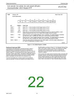
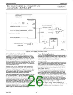
Figure 18. Block Diagram of Oscillator Control
CPU Clock Modification: CLKR and DIVM
Power Monitoring Functions
For backward compatibility, the CLKR configuration bit allows
setting the 87LPC764 instruction and peripheral timing to match
standard 80C51 timing by dividing the CPU clock by two. Default
timing for the 87LPC764 is 6 CPU clocks per machine cycle while
standard 80C51 timing is 12 clocks per machine cycle. This
division also applies to peripheral timing, allowing 80C51 code that
is oscillator frequency and/or timer rate dependent. The CLKR bit
is located in the EPROM configuration register UCFG1, described
under EPROM Characteristics
The 87LPC764 incorporates power monitoring functions designed to
prevent incorrect operation during initial power up and power loss or
reduction during operation. This is accomplished with two hardware
functions: Power-On Detect and Brownout Detect.
Brownout Detection
The Brownout Detect function allows preventing the processor from
failing in an unpredictable manner if the power supply voltage drops
below a certain level. The default operation is for a brownout
detection to cause a processor reset, however it may alternatively
be configured to generate an interrupt by setting the BOI bit in the
AUXR1 register (AUXR1.5).
In addition to this, the CPU clock may be divided down from the
oscillator rate by a programmable divider, under program control.
This function is controlled by the DIVM register. If the DIVM register
is set to zero (the default value), the CPU will be clocked by either
the unmodified oscillator rate, or that rate divided by two, as
determined by the previously described CLKR function.
The 87LPC764 allows selection of two Brownout levels: 2.5 V or
3.8 V. When V drops below the selected voltage, the brownout
DD
detector triggers and remains active until V is returns to a level
DD
above the Brownout Detect voltage. When Brownout Detect causes
When the DIVM register is set to some value N (between 1 and 255),
the CPU clock is divided by 2 * (N + 1). Clock division values from 4
through 512 are thus possible. This feature makes it possible to
temporarily run the CPU at a lower rate, reducing power consumption,
in a manner similar to Idle mode. By dividing the clock, the CPU can
retain the ability to respond to events other than those that can cause
interrupts (i.e. events that allow exiting the Idle mode) by executing its
normal program at a lower rate. This can allow bypassing the
oscillator startup time in cases where Power Down mode would
otherwise be used. The value of DIVM may be changed by the
program at any time without interrupting code execution.
a processor reset, that reset remains active as long as V remains
DD
below the Brownout Detect voltage. When Brownout Detect
generates an interrupt, that interrupt occurs once as V crosses
DD
from above to below the Brownout Detect voltage. For the interrupt
to be processed, the interrupt system and the BOI interrupt must
both be enabled (via the EA and EBO bits in IEN0).
When Brownout Detect is activated, the BOF flag in the PCON
register is set so that the cause of processor reset may be determined
by software. This flag will remain set until cleared by software.
23
2001 Oct 26

 NXP [ NXP ]