KMA220
NXP Semiconductors
Dual channel programmable angle sensor
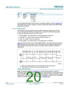
13.5 Registers
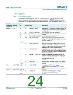
13.5.1 Command registers
To enter the command mode, write the signature given in Table 19 into the specific
register using the OWI. Do this procedure as described in Section 13.3.3, with a write
command, the signature follows it, but after a power-on reset and not later than tcmd(ent)
.
Table 19. Command registers
Command Register
write/read
Bit
Access Field
Description
82h/83h
CTRL1
15
R
IN_DIAG_MODE
shows if there is a diagnostic condition present; the
setting of register field FORCE_DIAG_OFF does
not affect this bit
14
13
12
11
W
-
FORCE_DIAG_OFF
-
force diagnostic mode off; default: 0b
reserved
R
LOW_VOLTAGE_DET low voltage condition detected
R/W
CP_CLOCK_EN
charge pump clock enabled (must be set after
setting write enable signal for writing to non-volatile
memory); default: 0b
10 and 9 -
-
reserved
8
7
6
R
ERR_CORRECT
single-bit error of non-volatile memory has been
detected and corrected; updated every memory
readout; remains set until the diagnostic condition
disappears and a power-on reset is done
R
R
UNCORR_ERR
double-bit error of non-volatile memory has been
detected; updated every memory readout; remains
set until the diagnostic condition disappears and a
power-on reset is done
MAGNET_LOSS_DET magnet-loss detected; bit remains set until the
diagnostic condition disappears and a power-on
reset is done; enable magnet-loss detection for
entering diagnostic mode
5
-
-
reserved
4
R
-
CRC_BAD
checksum error detected; updated every start-up
reserved
3 to 0
-
94h/-
SIGNATURE 15 to 0
W
SIGNATURE
write signature 16F4h within tcmd(ent) to enter
command mode; see Section 13.3.3 for more
details
96h/97h
TESTCTRL0 15 to 12
11
-
-
reserved
W
WRITE_EN
write enable signal; set before writing to
non-volatile memory; default: 0b
10 to 0
-
-
reserved
KMA220
All information provided in this document is subject to legal disclaimers.
© NXP B.V. 2012. All rights reserved.
Product data sheet
Rev. 1 — 24 May 2012
24 of 36

 NXP [ NXP ]