ISP1362
Single-chip USB OTG controller
Philips Semiconductors
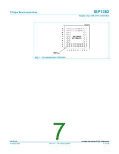
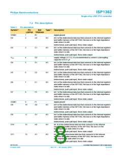
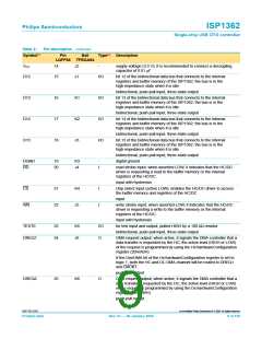
Table 2:
Symbol[1]
Pin description…continued
Pin Ball
LQFP64 TFBGA64
Type[2] Description
H_PSW2
36
G9
O
connects to the external PMOS switch
LOW — switches ON the PMOS providing VBUS to the downstream
port
HIGH — switches OFF the PMOS
when not in use, leave this pin open
open-drain output
DGND
37
38
G10
F9
-
digital ground
CLKOUT
O
programmable clock output; the default clock frequency is 12 MHz and
can be varied from 3 MHz to 48 MHz
push-pull output
GL
39
F10
O
GoodLink LED indicator output; the LED is OFF by default, blinks ON
upon USB traffic
open-drain output; 4 mA
VCC
40
41
E9
-
I
supply voltage (3.3 V); it is recommended to connect a decoupling
capacitor of 0.01 µF
H_OC2
E10
overcurrent sense input for downstream port 2; both the digital and
analog overcurrent inputs can be used for port 2, depending on the
hardware mode register setting; when not in use, it is recommended to
connect this pin to the VDD_5V pin
H_OC1
42
D9
I
overcurrent sensing input for downstream port 1; both the digital and
analog overcurrent inputs can be used for port 1, depending on the
hardware mode register setting; when not in use, it is recommended to
connect this pin to the VDD_5V pin
X1
43
44
45
D10
C9
AI
AO
I
crystal input; connected directly to a 12 MHz crystal; when this pin is
connected to an external clock oscillator, leave pin X2 open
X2
crystal output; connected directly to a 12 MHz crystal; when pin X1 is
connected to an external clock oscillator, leave this pin open
OTGMODE
C10
to select whether port 1 is operating in the OTG or non-OTG mode;
see Table 8
input with hysteresis
H_DM2
H_DP2
ID
46
47
48
B9
AI/O
AI/O
I
downstream D− signal; host only, port 2; when not in use, leave this
pin open and set bit ConnectPullDown_DS2 of the
HcHardwareConfiguration register
B10
A10
downstream D+ signal; host only, port 2; when not in use, leave this
pin open and set bit ConnectPullDown_DS2 of the
HcHardwareConfiguration register
input pin for sensing OTG ID; the status of this input pin is reflected in
the OTGStatus register (bit 0); see Table 8
input with hysteresis
OTG_DM1
OTG_DP1
49
50
A9
B8
AI/O
AI/O
D− signal of the OTG port, the downstream host port 1 or the
upstream device port; when not in use, leave this pin open and set
bit ConnectPullDown_DS1 of the HcHardwareConfiguration register[3]
D+ signal of the OTG port, the downstream host port 1 or the
upstream device port; when not in use, leave this pin open and set
bit ConnectPullDown_DS1 of the HcHardwareConfiguration register[3]
9397 750 12337
© Koninklijke Philips Electronics N.V. 2004. All rights reserved.
Product data
Rev. 03 — 06 January 2004
11 of 150

 NXP [ NXP ]