ISP1160
Embedded USB Host Controller
Philips Semiconductors
18. Application information
18.1 Typical interface circuit
V
DD
+
+
3.3 V
+
+
+
5 V
5 V
5 V 3.3 V
MOSFET
(2×)
SH7709
ISP1160
Vbus_DN2 Vbus_DN1
V
CC
+
+
3.3 V
5 V
H_OC1_N
H_OC2_N
H_PSW2_N
[
]
[
]
D 15:0
D 15:0
FB1
22 Ω
(2×)
H_PSW1_N
A1
A0
USB
downstream
port #1
H_DM1
H_DP1
H_DM2
H_DP2
CS5
RD_N
RD/WR_N
CS_N
RD_N
WR_N
47 pF
(2×)
FB2
DREQ0
DACK0_N
DREQ
DACK_N
V
reg
+
3.3 V
FB3
V
(3V3)
REG
22 Ω
+
5 V
EOT
(2×)
USB
downstream
port #2
CLKOUT
EXTAL
XTAL
V
1
V
DD
HOLD
IRQ2
INT
V
HOLD2
47 pF
(2×)
FB4
PTC0
PTC1
H_WAKEUP
H_SUSPEND
NDP_SEL
EXTAL2
XTAL2
GND
32
kHz
RESET_N
RSTOUT
XTAL2
XTAL1
6 MHz
7
DGND
AGND
22 pF
22 pF
004aaa072
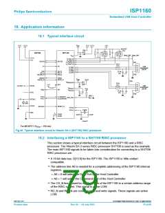
For MOSFET, RDSon = 150 mΩ.
Fig 40. Typical interface circuit to Hitachi SH-3 (SH7709) RISC processor.
18.2 Interfacing a ISP1160 to a SH7709 RISC processor
This section shows a typical interface circuit between the ISP1160 and a RISC
processor. The Hitachi SH-3 series RISC processor SH7709 is used as the example.
The main ISP1160 signals to be taken into consideration for connecting to a SH7709
RISC processor are:
• A 16-bit data bus: D[15:0] for the ISP1160. The ISP1160 is ‘little endian’
compatible.
• The address line A0 is needed for a complete addressing of the ISP1160 internal
registers:
– A0 = 0 will select the Data Port of the Host Controller
– A0 = 1 will select the Command Port of the Host Controller
• The CS_N line is used for chip selection of the ISP1160 in a certain address range
of the RISC system. This signal is active LOW.
• RD_N and WR_N are common read and write signals. These signals are active
LOW.
9397 750 11371
© Koninklijke Philips Electronics N.V. 2003. All rights reserved.
Product data
Rev. 04 — 04 July 2003
79 of 88

 NXP [ NXP ]