ISP1160
Embedded USB Host Controller
Philips Semiconductors
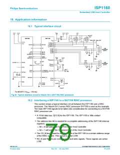
• There is a DMA channel standard control line: DREQ and DACK_N. The DREQ
signal has programmable active levels.
• An interrupt line INT is used by the HC. It has programmable level/edge and
polarity (active HIGH or LOW).
• The internal 15 kΩ pull-down resistors are used for the HC’s two USB downstream
ports.
• The RESET_N signal is active LOW.
Remark: SH7709’s system clock input is for reference only. Refer to SH7709’s
specification for its actual use.
The ISP1160 can work under either 3.3 V or 5.0 V power supply; however, its internal
core works at 3.3 V. When using 3.3 V as the power supply input, the internal DC/DC
regulator will be bypassed. It is best to connect all four power supply pins (VCC
,
VREG(3V3), VHOLD1 and VHOLD2) to the 3.3 V power supply (for more information, see
Section 11). All of the ISP1160’s I/O pins are 5 V-tolerant. This feature allows the
ISP1160 the flexibility to be used in an embedded system under either a 3.3 V or a
5 V power supply.
A typical SH7709 interface circuit is shown in Figure 40.
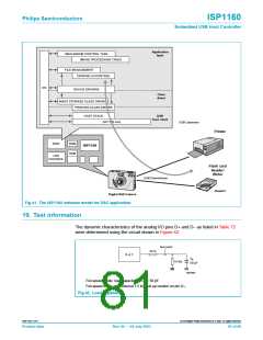
18.3 Typical software model
This section shows a typical software requirement for an embedded system that
incorporates the ISP1160. The software model for a Digital Still Camera (DSC) is
used as the example for illustration (as shown in Figure 41). The host stack provides
API for Class driver and device driver, both of which provide API for application tasks
for host function.
9397 750 11371
© Koninklijke Philips Electronics N.V. 2003. All rights reserved.
Product data
Rev. 04 — 04 July 2003
80 of 88

 NXP [ NXP ]