ISP1160
Embedded USB Host Controller
Philips Semiconductors
V
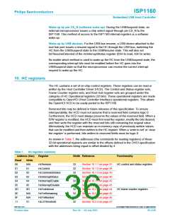
BUS
USB
connector
ISP1160
22 Ω
22 Ω
D−
D+
bit 12
HcHardware
Configuration
47 pF
(2×)
external
15 kΩ
(2×)
internal
15 kΩ
(2×)
004aaa064
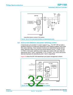
Using either internal or external 15 kΩ resistors.
Fig 24. Use of 15 kΩ pull-down resistors on downstream ports.
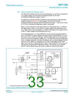
9.8 Overcurrent detection and power switching control
A downstream port provides 5 V power supply to VBUS. The ISP1160 has built-in
hardware functions to monitor the downstream ports loading conditions and control
their power switching. These hardware functions are implemented by the internal
power switching control circuit and overcurrent detection circuit. H_PSW1_N and
H_PSW2_N are power switching control output pins (active LOW, open-drain) for
downstream ports 1 and 2, respectively. H_OC1_N and H_OC2_N are overcurrent
detection input pins for downstream ports 1 and 2, respectively.
Figure 25 shows the ISP1160 downstream port power management scheme.
regulator
HC CORE
HcHardware
V
CC
(+5 V or +3.3 V)
OC detect
Configuration
OC select
1
bit 10
≥
H_OCn_N
0
Reg
PSW
H_PSWn_N
C/L
ISP1160
004aaa065
’n’ represents the downstream port numbers (n = 1 or 2).
Fig 25. Downstream port power management scheme.
9397 750 11371
© Koninklijke Philips Electronics N.V. 2003. All rights reserved.
Product data
Rev. 04 — 04 July 2003
32 of 88

 NXP [ NXP ]