ISP1160
Embedded USB Host Controller
Philips Semiconductors
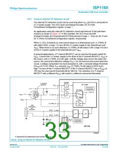
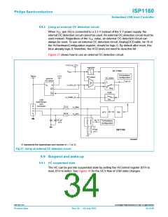
9.8.2 Using an external OC detection circuit
When VCC (pin 56) is connected to a 3.3 V instead of the 5 V power supply, the
internal OC detection circuit cannot be used. An external OC detection circuit must be
used instead. Regardless of the VCC value, an external OC detection circuit can
always be used. To use an external OC detection circuit, AnalogOCEnable, bit 10 of
the HcHardwareConfiguration register, should be logic 0. By default after reset, this
bit is already logic 0; therefore, the HCD does not need to clear this bit.
Figure 27 shows how to use an external OC detection circuit.
+
+
3.3 V or 5 V
regulator
HC CORE
HcHardware
V
CC
V
+
5 V
BUS
OC detect
Configuration
OC select
external
OC detect
bit 10
1
≥
V
V
i
H_OCn_N
o
0
Reg
OC
EN
PSW
H_PSWn_N
C/L
USB
downstream
port
connector
22 Ω
H_DMn
H_DPn
ATX
SIE
22 Ω
bit 12
47 pF
(2×)
HcHardware
Configuration
15 kΩ
(2×)
ISP1160
004aaa067
’n’ represents the downstream port number (n = 1 or 2).
Fig 27. Using an external OC detection circuit.
9.9 Suspend and wake-up
9.9.1 HC suspended state
The HC can be put into suspended state by setting the HcControl register (01H to
read, 81H to write). See Figure 14 for the HC’s flow of USB state changes.
9397 750 11371
© Koninklijke Philips Electronics N.V. 2003. All rights reserved.
Product data
Rev. 04 — 04 July 2003
34 of 88

 NXP [ NXP ]