ISP1160
Embedded USB Host Controller
Philips Semiconductors
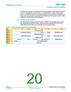
The PTD data structure is used by the HC to define a buffer of data that will be moved
to or from an endpoint in the USB device. This data buffer is set up for the current
frame (1 ms frame) by the HCD. The payload data for every transfer in the frame must
have a PTD as the header to describe the characteristic of the transfer. The PTD data
is DWORD (double-word or 4-byte) aligned.
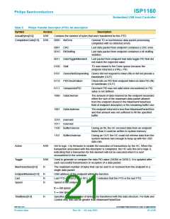
9.3.1 PTD data header definition
The PTD forms the header of the PTD data. It tells the HC the transfer type, where
the payload data should go, and the actual size of the payload data. A PTD is an
8-byte data structure that is very important for HCD programming.
Table 4:
Bit
Philips Transfer Descriptor (PTD): bit allocation
7
6
5
4
3
2
1
0
Byte 0
Byte 1
Byte 2
Byte 3
Byte 4
Byte 5
Byte 6
Byte 7
ActualBytes[7:0]
Active
CompletionCode[3:0]
EndpointNumber[3:0]
Toggle
Speed
ActualBytes[9:8]
MaxPacketSize[9:8]
TotalBytes[9:8]
MaxPacketSize[7:0]
Last
TotalBytes[7:0]
reserved
B5_5
reserved
DirectionPID[1:0]
Format
FunctionAddress[6:0]
reserved
9397 750 11371
© Koninklijke Philips Electronics N.V. 2003. All rights reserved.
Product data
Rev. 04 — 04 July 2003
20 of 88

 NXP [ NXP ]