PFS122
8bit MTP MCU with 12-bit R-Type ADC
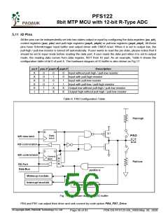
All the IO pins have the same structure. The corresponding bits in registers padier / pbdier should be set to
low to prevent leakage current for those pins are selected to be analog function. When PFS122 is put in
power-down or power-save mode, every pin can be used to wake-up system by toggling its state. Therefore,
those pins needed to wake-up system must be set to input mode and set the corresponding bits of registers
pxdier to high. The same reason, padier.0 should be set high when PA0 is used as external interrupt pin,
and so for other external interrupt pins: PB0, PA4 and PB5.
5.12 Reset and LVR
5.12.1 Reset
There are many causes to reset the PFS122, once reset is asserted, most of all the registers in PFS122
will be set to default values, system should be restarted once abnormal cases happen, or by jumping
program counter to address 0x0. The data memory is in uncertain state when reset comes from power-up
and LVR; however, the content will be kept when reset comes from PRSTB pin or WDT timeout.
5.12.2 LVR reset
By code option, there are many different levels of LVR for reset. Usually, user selects LVR reset level to be
in conjunction with operating frequency and supply voltage.
5.13 Analog-to-Digital Conversion (ADC) module
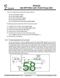
Fig. 18: ADC Block Diagram
©Copyright 2020, PADAUK Technology Co. Ltd
Page 57 of 93
PDK-DS-PFS122-EN_V000-May 28, 2020

 PADAUK [ PADAUK Technology ]