PFS122
8bit MTP MCU with 12-bit R-Type ADC
Example 3:
tm2c = 0b0001_1010, Y=8MHz
tm2b = 0b0011_1111, K=63
tm2s = 0b1_00_00000, S1=1, S2=0
PWM output keep high
duty of output = [(63+1) ÷ 64] × 100% = 100%
Example 4:
tm2c = 0b0001_1010, Y=8MHz
tm2b = 0b0000_0000, K=0
tm2s = 0b1_00_00000, S1=1, S2=0
frequency = 8MHz ÷ ( 64 × 1 × (0+1) ) = 125KHz
duty = [(0+1) ÷ 64] × 100% =1.5%
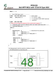
5.7.4 Complementary PWM with Dead Zones
User can get complementary PWM with dead zones by employing TM2 and TM3. Here provide an
example in which duty cycle and dead time are adjustable.
//------- These two parameters need be defined when T(PWM) = 256 us ----------
#define
#define
PWM_pulse
dead_zone
70
30
// 70 us; Adjust it for a different duty cycle of TM2/TM3.
// 30 us; Adjust it for the best dead time.
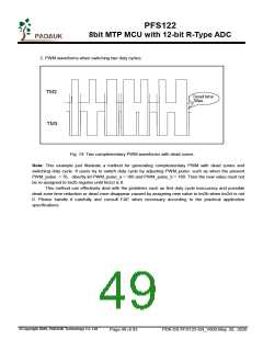
//--------Parameters for switching duty cycle -----------------------------------
#define
#define
#define
PWM_Pulse_a
PWM_Pulse_b
t_delay
100 // 100 us; Adjust it for a different duty cycle of TM2/TM3
160 // 160 us; Adjust it for a different duty cycle of TM2/TM3
500 // 500 us; Switching time of duty cycle
void
{
FPPA0 (void)
// SYSCLK must quicker than Timer2’s clock. Here set SYSCLK=2MHz to capture Tm2ct = 0.
.ADJUST_IC SYSCLK=IHRC/8, IHRC=16MHz, VDD=3.3V, Init_ram;
//******Generate complementary PWM with dead zones in a fixed-duty cycle****************
//------Set the counter upper bound, duty cycle and TMXCT -----------
$ TM2S 8BIT,/4,/4
TM2B
// 16MHz /4 /4 /256 = 1MHz / 256 =
256 us
=
PWM_pulse - 1;
$ TM3S 8BIT,/4,/4
// 16MHz /4 /4 /256
TM3B
=
=
PWM_pulse + 2 * dead_zone - 1;
0;
TM2CT
©Copyright 2020, PADAUK Technology Co. Ltd
Page 47 of 93
PDK-DS-PFS122-EN_V000-May 28, 2020

 PADAUK [ PADAUK Technology ]