PFS122
8bit MTP MCU with 12-bit R-Type ADC
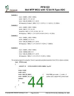
The sample program for using the Timer2 to generate PWM waveform from PA3 is shown as below:
void
{
FPPA0 (void)
.ADJUST_IC
SYSCLK=IHRC/2, IHRC=16MHz, VDD=5V
tm2ct = 0x00;
tm2b = 0x7f;
tm2s = 0b0_00_00001;
//
//
8-bit PWM, pre-scalar = 1, scalar = 2
system clock, output=PA3, PWM mode
tm2c = 0b0001_10_1_0;
while(1)
{
nop;
}
}
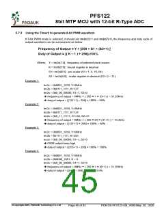
5.7.3 Using the Timer2 to generate 6-bit PWM waveform
If 6-bit PWM mode is selected, it should set tm2c[1]=1 and tm2s[7]=1, the frequency and duty cycle of
output waveform can be summarized as below:
Frequency of Output = Y ÷ [64 × S1 × (S2+1) ]
Duty of Output = [( K+1 ) ÷ 64] × 100%
Where, tm2c[7:4] = Y : frequency of selected clock source
tm2b[7:0] = K : bound register in decimal
tm2s[6:5] = S1 : pre-scalar (S1= 1, 4, 16, 64)
tm2s[4:0] = S2 : scalar register in decimal (S2= 0 ~ 31)
Users can set Timer2 to be 7-bit PWM mode instead of 6-bit mode by using TMx_Bit code option. At that
time, the calculation factors of the above equations become 128 instead of 64.
Example 1:
tm2c = 0b0001_1010, Y=8MHz
tm2b = 0b0001_1111, K=31
tm2s = 0b1_00_00000, S1=1, S2=0
frequency of output = 8MHz ÷ ( 64 × 1 × (0+1) ) = 125KHz
duty = [(31+1) ÷ 64] × 100% = 50%
Example 2:
tm2c = 0b0001_1010, Y=8MHz
tm2b = 0b0001_1111, K=31
tm2s = 0b1_11_11111, S1=64, S2=31
frequency of output = 8MHz ÷ ( 64 × 64 × (31+1) ) = 61.03 Hz
duty of output = [(31+1) ÷ 64] × 100% = 50%
©Copyright 2020, PADAUK Technology Co. Ltd
Page 46 of 93
PDK-DS-PFS122-EN_V000-May 28, 2020

 PADAUK [ PADAUK Technology ]