PFS122
8bit MTP MCU with 12-bit R-Type ADC
Time out and
Time out and
Time out and
Interrupt request
Interrupt request
Interrupt request
Counter
0xFF
bound
Counter
0xFF
Counter
0x3F
bound
bound
Time
Time
Time
Time
Time
Event Trigger
Event Trigger
Event Trigger
Output-pin
Output-pin
Output-pin
Time
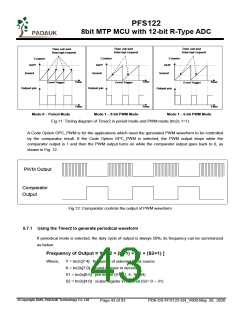
Mode 0 – Period Mode
Mode 1 – 8-bit PWM Mode
Mode 1 – 6-bit PWM Mode
Fig.11: Timing diagram of Timer2 in period mode and PWM mode (tm2c.1=1)
A Code Option GPC_PWM is for the applications which need the generated PWM waveform to be controlled
by the comparator result. If the Code Option GPC_PWM is selected, the PWM output stops while the
comparator output is 1 and then the PWM output turns on while the comparator output goes back to 0, as
shown in Fig. 12.
PWM Output
Comparator
Output
Fig.12: Comparator controls the output of PWM waveform
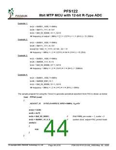
5.7.1 Using the Timer2 to generate periodical waveform
If periodical mode is selected, the duty cycle of output is always 50%; its frequency can be summarized
as below:
Frequency of Output = Y ÷ [2 × (K+1) × S1 × (S2+1) ]
Where,
Y = tm2c[7:4] : frequency of selected clock source
K = tm2b[7:0] : bound register in decimal
S1 = tm2s[6:5] : pre-scalar (S1= 1, 4, 16, 64)
S2 = tm2s[4:0] : scalar register in decimal (S2= 0 ~ 31)
©Copyright 2020, PADAUK Technology Co. Ltd
Page 43 of 93
PDK-DS-PFS122-EN_V000-May 28, 2020

 PADAUK [ PADAUK Technology ]