PFS122
8bit MTP MCU with 12-bit R-Type ADC
5.8 WatchDog Timer
The watchdog timer (WDT) is a counter with clock coming from ILRC. WDT can be cleared by power-on-reset
or by command wdreset at any time. There are four different timeout periods of watchdog timer to be chosen
by setting the misc register, it is:
8k ILRC clocks period if register misc[1:0]=00 (default)
16k ILRC clocks period if register misc[1:0]=01
64k ILRC clocks period if register misc[1:0]=10
256k ILRC clocks period if register misc[1:0]=11
The frequency of ILRC may drift a lot due to the variation of manufacture, supply voltage and temperature;
user should reserve guard band for save operation. Besides, the watchdog period will also be shorter than
expected after Reset or Wakeup events. It is suggested to clear WDT by wdreset command after these
events to ensure enough clock periods before WDT timeout.
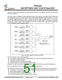
When WDT is timeout, PFS122 will be reset to restart the program execution. The relative timing diagram of
watchdog timer is shown as Fig.15.
VDD
t
SBP
WD
Time Out
Program
Execution
Watch Dog Time Out Sequence
Fig.15: Sequence of Watch Dog Time Out
5.9 Interrupt
There are seven interrupt lines for PFS122:
External interrupt PA0/PB5
External interrupt PB0/PA4
ADC interrupt
Timer16 interrupt
GPC interrupt
Timer2 interrupt
Timer3 interrupt
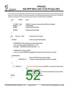
Every interrupt request line has its own corresponding interrupt control bit to enable or disable it; the
hardware diagram of interrupt function is shown as Fig.16. All the interrupt request flags are set by hardware
and cleared by writing intrq register. When the request flags are set, it can be rising edge, falling edge or both,
depending on the setting of register integs. All the interrupt request lines are also controlled by engint
©Copyright 2020, PADAUK Technology Co. Ltd
Page 50 of 93
PDK-DS-PFS122-EN_V000-May 28, 2020

 PADAUK [ PADAUK Technology ]