PFS122
8bit MTP MCU with 12-bit R-Type ADC
instruction (enable global interrupt) to enable interrupt operation and disgint instruction (disable global
interrupt) to disable it.
The stack memory for interrupt is shared with data memory and its address is specified by stack register sp.
Since the program counter is 16 bits width, the bit 0 of stack register sp should be kept 0. Moreover, user can
use pushaf / popaf instructions to store or restore the values of ACC and flag register to / from stack
memory. Since the stack memory is shared with data memory, the stack position and level are arranged by
the compiler in Mini-C project. When defining the stack level in ASM project, users should arrange their
locations carefully to prevent address conflicts.
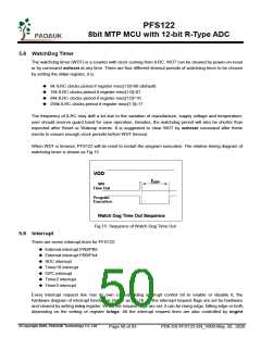
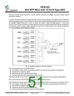
Fig.16: Hardware diagram of interrupt controller
Once the interrupt occurs, its operation will be:
The program counter will be stored automatically to the stack memory specified by register sp.
New sp will be updated to sp+2.
Global interrupt will be disabled automatically.
The next instruction will be fetched from address 0x010.
During the interrupt service routine, the interrupt source can be determined by reading the intrq register.
Note: Even if INTEN=0, INTRQ will be still triggered by the interrupt source.
After finishing the interrupt service routine and issuing the reti instruction to return back, its operation will be:
The program counter will be restored automatically from the stack memory specified by register sp.
New sp will be updated to sp-2.
Global interrupt will be enabled automatically.
The next instruction will be the original one before interrupt.
©Copyright 2020, PADAUK Technology Co. Ltd
Page 51 of 93
PDK-DS-PFS122-EN_V000-May 28, 2020

 PADAUK [ PADAUK Technology ]