PFS122
8bit MTP MCU with 12-bit R-Type ADC
TM3CT
=
0;
//------Timer PWM output control -------------------
$ TM3C
.delay
IHRC, PB5, PWM, Inverse;
dead_zone*2 - 2;
// Inverse output
// "*2": SYSCLK = 2MHz
// "-2": executing “$ TM3C XXXX” needs two
//
instructions
$ TM2C
IHRC, PB4, PWM;
//***Note: Do not change the sequence of the control part’s program*****
//-------Following codes can be for reference when user needs switch duty cycle ----------
//------ Switching PWM_pulse -------------------
While (1)
{
While(tm2ct!=0)
{}
// Wait till tm2ct=0 to avoid noise
TM2B
TM3B
.delay
=
=
PWM_Pulse_a - 1;
PWM_Pulse_a + 2 * dead_zone - 1;
t_delay*2;
While(tm2ct!=0) {}
TM2B
TM3B
.delay
=
=
PWM_Pulse_b - 1;
PWM_Pulse_b + 2 * dead_zone - 1;
t_delay*2;
}
}
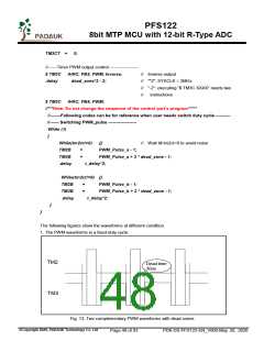
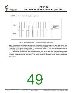
The following figures show the waveforms at different condition.
1. The PWM waveforms in a fixed-duty cycle:
TM2
Dead time
30us.
TM3
Fig. 13: Two complementary PWM waveforms with dead zones
©Copyright 2020, PADAUK Technology Co. Ltd
Page 48 of 93
PDK-DS-PFS122-EN_V000-May 28, 2020

 PADAUK [ PADAUK Technology ]