PFS122
8bit MTP MCU with 12-bit R-Type ADC
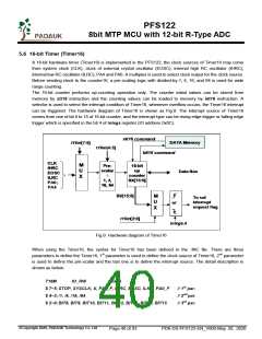
User can define the parameters of T16M based on system requirement, some examples are shown below
and more examples please refer to “Application Note IC Introduction Register Introduction T16M” in
IDE utility.
$ T16M SYSCLK, /64, BIT15;
// choose (SYSCLK/64) as clock source, every 2^16 clock to set INTRQ.2=1
// if using System Clock = IHRC / 2 = 8 MHz
// SYSCLK/64 = 8 MHz/64 = 125KHz, about every 512 mS to generate INTRQ.2=1
$ T16M EOSC, /1, BIT13;
// choose (EOSC/1) as clock source, every 2^14 clocks to generate INTRQ.2=1
// if EOSC=32768 Hz, 32768 Hz/(2^14) = 2Hz, every 0.5S to generate INTRQ.2=1
$ T16M PA0_F, /1, BIT8;
// choose PA0 as clock source, every 2^9 to generate INTRQ.2=1
// receiving every 512 times PA0 to generate INTRQ.2=1
$ T16M STOP;
// stop Timer16 counting
If Timer16 is operated at free running, the frequency of interrupt can be described as below:
FINTRQ_T16M = Fclock source ÷ P ÷ 2n+1
Where, F is the frequency of selected clock source to Timer16;
P is the selection of t16m [4:3]; (1, 4, 16, 64)
N is the nth bit selected to request interrupt service, for example: n=10 if bit 10 is selected.
©Copyright 2020, PADAUK Technology Co. Ltd
Page 41 of 93
PDK-DS-PFS122-EN_V000-May 28, 2020

 PADAUK [ PADAUK Technology ]