PFS122
8bit MTP MCU with 12-bit R-Type ADC
5.6 16-bit Timer (Timer16)
A 16-bit hardware timer (Timer16) is implemented in the PFS122, the clock sources of Timer16 may come
from system clock (CLK), clock of external crystal oscillator (EOSC), internal high RC oscillator (IHRC),
internal low RC oscillator (ILRC), PA4 and PA0. A multiplex is used to select clock output for the clock source.
Before sending clock to the counter16, a pre-scaling logic with divided-by-1, 4, 16, and 64 is used for wide
range counting.
The 16-bit counter performs up-counting operation only. The counter initial values can be stored from
memory by stt16 instruction and the counting values can be loaded to memory by ldt16 instruction. A
selector is used to select the interrupt condition of Timer16, whenever overflow occurs, the Timer16 interrupt
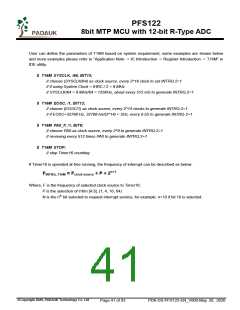
can be triggered. The hardware diagram of Timer16 is shown as Fig.9. The interrupt source of Timer16
comes from one of bit 8 to 15 of 16-bit counter, and the interrupt type can be rising edge trigger or falling edge
trigger which is specified in the bit 4 of integs register (IO address 0x0C).
PA4
Fig.9: Hardware diagram of Timer16
When using the Timer16, the syntax for Timer16 has been defined in the .INC file. There are three
parameters to define the Timer16; 1st parameter is used to define the clock source of Timer16, 2nd parameter
is used to define the pre-scalar and the last one is to define the interrupt source. The detail description is
shown as below:
T16M
IO_RW
0x06
$ 7~5:STOP, SYSCLK, X, PA4_F, IHRC, EOSC, ILRC, PA0_F
$ 4~3:/1, /4, /16, /64
// 1st par.
// 2nd par.
// 3rd par.
$ 2~0:BIT8, BIT9, BIT10, BIT11, BIT12, BIT13, BIT14, BIT15
©Copyright 2020, PADAUK Technology Co. Ltd
Page 40 of 93
PDK-DS-PFS122-EN_V000-May 28, 2020

 PADAUK [ PADAUK Technology ]