PFS122
8bit MTP MCU with 12-bit R-Type ADC
5.4.5. System Clock and LVR level
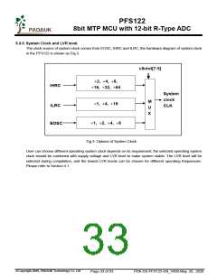
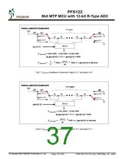
The clock source of system clock comes from EOSC, IHRC and ILRC, the hardware diagram of system clock
in the PFS122 is shown as Fig.3.
clkmd[7:5]
÷2, ÷4, ÷8,
IHRC
÷16, ÷32, ÷64
System
clock
M
÷1, ÷4, ÷16
ILRC
CLK
U
X
÷1, ÷2, ÷4, ÷8
EOSC
Fig.3: Options of System Clock
User can choose different operating system clock depends on its requirement; the selected operating system
clock should be combined with supply voltage and LVR level to make system stable. The LVR level will be
selected during compilation, and the lowest LVR levels can be chosen for different operating frequencies.
Please refer to Section 4.1.
©Copyright 2020, PADAUK Technology Co. Ltd
Page 33 of 93
PDK-DS-PFS122-EN_V000-May 28, 2020

 PADAUK [ PADAUK Technology ]