PFS122
8bit MTP MCU with 12-bit R-Type ADC
5.3. Data Memory - SRAM
The access of data memory can be byte or bit operation. Besides data storage, the SRAM data memory is
also served as data pointer of indirect access method and the stack memory.
The stack memory is defined in the data memory. The stack pointer is defined in the stack pointer register; the
depth of stack memory of each processing unit is defined by the user. The arrangement of stack memory fully
flexible and can be dynamically adjusted by the user.
For indirect memory access mechanism, the data memory is used as the data pointer to address the data
byte. All the data memory could be the data pointer; it’s quite flexible and useful to do the indirect memory
access. Since the data width is 8-bit, all the 128 bytes data memory of PFS122 can be accessed by indirect
access mechanism.
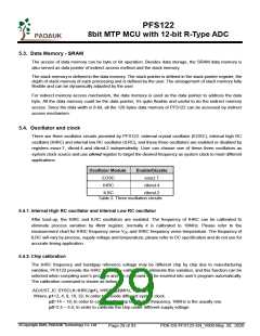
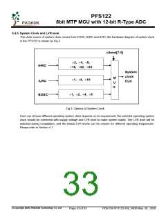
5.4. Oscillator and clock
There are three oscillator circuits provided by PFS122: external crystal oscillator (EOSC), internal high RC
oscillator (IHRC) and internal low RC oscillator (ILRC), and these three oscillators are enabled or disabled by
registers eoscr.7, clkmd.4 and clkmd.2 independently. User can choose one of these three oscillators as
system clock source and use clkmd register to target the desired frequency as system clock to meet different
applications.
Oscillator Module
EOSC
Enable/Disable
eoscr.7
IHRC
clkmd.4
ILRC
clkmd.2
Table 2: Three oscillation circuits
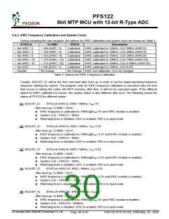
5.4.1. Internal High RC oscillator and Internal Low RC oscillator
After boot-up, the IHRC and ILRC oscillators are enabled. The frequency of IHRC can be calibrated to
eliminate process variation by ihrcr register; normally it is calibrated to 16MHz. Please refer to the
measurement chart for IHRC frequency verse VDD and IHRC frequency verse temperature. The frequency of
ILRC will vary by process, supply voltage and temperature, please refer to DC specification and do not use for
accurate timing application.
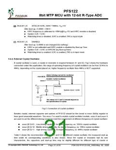
5.4.2. Chip calibration
The IHRC frequency and bandgap reference voltage may be different chip by chip due to manufacturing
variation, PFS122 provide the IHRC frequency calibration to eliminate this variation, and this function can be
selected when compiling user’s program and the command will be inserted into user’s program automatically.
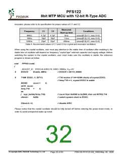
The calibration command is shown as below:
.ADJUST_IC SYSCLK=IHRC/(p1), IHRC=(p2)MHz, VDD=(p3)V;
Where, p1=2, 4, 8, 16, 32; In order to provide different system clock.
p2=14 ~ 18; In order to calibrate the chip to different frequency, 16MHz is the usually one.
p3=2.5 ~ 5.5; In order to calibrate the chip under different supply voltage.
©Copyright 2020, PADAUK Technology Co. Ltd
Page 29 of 93
PDK-DS-PFS122-EN_V000-May 28, 2020

 PADAUK [ PADAUK Technology ]