NCP5392P
Final Equations for the Current Limit Threshold
Final equations are described based on two conditions: normal mode and PSI mode.
2V@R
LIM2
R
)R
(Vin * N @ Vout) @ Vout
L @ FSW @ Vin
LIM1
LIM2
ILIMIT(normal) ^
* 0.5 @
R
@(R
)R )R
ISO2
)
T2
)R )@R
SUM
NOR
)R
ISO1
4 @ (R
@ DCR25C(1 ) 0.00393 @ (Tinductor * 25))
@ COEpsi
LIM2
(eq. 7)
)R
T2
NOR
ISO1
ISO2
2V@R
LIM2
)R
R
(Vin * Vout) @ Vout
L @ FSW @ Vin
LIM1
)R )
ISO2
ILIMIT(PSI) ^
* 0.5 @
(eq. 8)
R
@(R
)R
T2
@ DCR25C(1 ) 0.00393 @ (Tinductor * 25))
)R )@R
SUM
NOR
)R
ISO1
)R
4 @ (R
T2
NOR
ISO1
ISO2
Inductor Current Sensing Compensation
N is the number of phases involved in the circuit.
The inductors on the demo board have a DCR at 25°C of
0.6ꢁmW. Selecting the closest available values of 21.3 kW
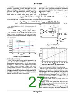
The NCP5392P uses the inductor current sensing
method. An RC filter is selected to cancel out the
impedance from inductor and recover the current
information through the inductor's DCR. This is done by
matching the RC time constant of the sensing filter to the
L/DCR time constant. The first cut approach is to use a 0.1
mF capacitor for C and then solve for R.
for R
and 9.28 kW for R
yields a nominal
operating frequency of 330 kHz. Select R 1 = 1ꢁk, R
LIM1
LIM2
ISO
ISO2
= 1 k, R = 10 K (25°C), R
/R
= 2, (refer to
T2
NOR SUM
application diagram). That results to an approximate
current limit of 133ꢁA at 100°C for a four phase operation
and 131ꢁA at 25°C. The total sensed current can be
observed as a scaled voltage at the VDRP with a positive
no-load offset of approximately 1.3 V.
(eq. 9)
L
Rsense(T) +
0.1 @ mF @ DCR25C @ (1 ) 0.00393(T * 25))
Because the inductor value is a function of load and
inductor temperature final selection of R is best done
Inductor Selection
When using inductor current sensing it is recommended
that the inductor does not saturate by more than 10% at
maximum load. The inductor also must not go into hard
saturation before current limit trips. The demo board
includes a four phase output filter using the T44-8 core
from Micrometals with 3 turns and a DCR target of 0.6ꢁmW
@ 25°C. Smaller DCR values can be used, however,
current sharing accuracy and droop accuracy decrease as
DCR decreases. Use the NCP5392P design aide for
regulation accuracy calculations for specific value of DCR.
experimentally on the bench by monitoring the V
droop
and performing a step load test on the actual solution.
pin
http://onsemi.com
24

 ONSEMI [ ONSEMI ]