NCP5392P
Dynamic VID Testing
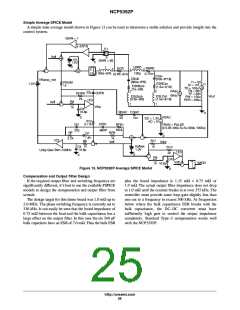
Understanding Soft-Start
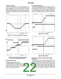
The VTT tool provides for VID stepping based on the
Intel Requirements. Select the Dynamic VID option.
Before enabling the test set the lowest VID to 0.5ꢁV or
greater and set the highest VID to a value that is greater than
the lowest VID selection, then enable the test. See Figures
7 and 8.
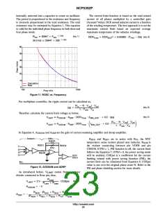
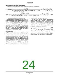
The controller supports two different startup routines. An
AMD ramp to the initial VID code, or a VR11 Ramp to the
1.1ꢁV boot voltage, with a pause to capture the VID code
then resume ramping to target value based on internal slew
rate limit. The initial ramp rate was set to be 0.8 mV/mS.
Figure 9. VR11.1 Startup
Figure 7. 1.6 V to 0.5 V Dynamic VID response
Figure 10. AMD Startup
Figure 8. Dynamic VID Settling Time Rising
(CH1: VID1, CH2: DAC, CH3:VCCP)
Programming the Current Limit and the Oscillator
Frequency
The demo board is set for an operating frequency of
pin provides a 2.0ꢁV
Design Methodology
approximately 330ꢁkHz. The R
OSC
reference voltage which is divided down with a resistor
divider and fed into the current limit pin ILIM. Then
calculate the individual RLIM1 and RLIM2 values for the
divider. The series resistors RLIM1 and RLIM2 sink
current from the ILIM pin to ground. This current is
Decoupling the VCC Pin on the IC
An RC input filter is required as shown in the V pin to
minimize supply noise on the IC. The resistor should be
sized such that it does not generate a large voltage drop
between 5ꢁV supply and the IC.
CC
http://onsemi.com
22

 ONSEMI [ ONSEMI ]