NCP5392P
Auto-PSI Function:
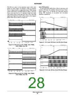
PH_PSI) are active in the emulation mode while other
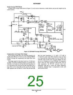
phases are shed. Figure 19 indicates a PSI-on transition
from a 3-phase mode to a single phase mode. While staying
stable in PSI mode, the PWM signal of phase 1 will vary
from a mid-state level (1.5 V typical) to high level while
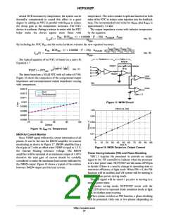
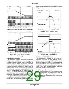
other phases all go to mid-state level. Vice verse, when PSI
signal goes high, the system will go back to the original
phase mode such as shown in Figure 20.
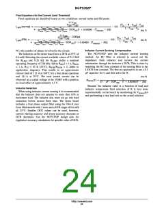
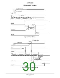
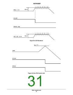
In Auto-PSI mode (APSI_EN=1, PSI=1), the device will
monitor VID lines for transition into/out-of Low Power
States. Figure 21 to 24 describe the Auto-PSI function
during VID transitions, in one-phase and two-phase
operation respectively.
Figure 21. 10 A Load, VID Down, into PSI (One Phase)
Figure 19. PSI turns on, CH1: PWM1, CH2: PWM2,
CH3: PWM3, CH4: PSI
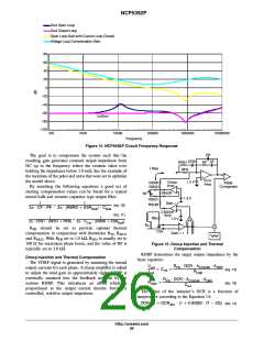
Figure 22. 10 A Load, VID Up, Out of PSI (One Phase)
Figure 20. PSI turns off, CH1: PWM1, CH2: PWM2,
CH3: PWM3, CH4: PSI
http://onsemi.com
28

 ONSEMI [ ONSEMI ]