NCP5392P
FUNCTIONAL DESCRIPTION
General
High Performance Voltage Error Amplifier
The NCP5392P provides up to four-phase buck solution
The error amplifier is designed to provide high slew rate
and bandwidth. Although not required when operating as
the controller of a voltage regulator, a capacitor from
COMP to VFB is required for stable unity gain test
configurations.
which combines differential voltage sensing, differential
phase current sensing, and adaptive voltage positioning to
provide accurately regulated power necessary for both
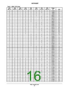
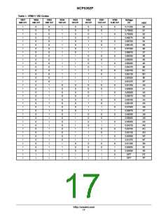
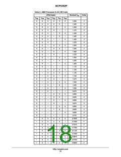
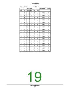
Intel VR11.1 and AMD CPU power system. NCP5392P has
been designed to work with the NCP5359 driver.
Gate Driver Outputs and 2/3/4 Phase Operation
The part can be configured to run in 2-, 3-, or 4-phase
mode. In 2-phase mode, phases 1 and 3 should be used to
drive the external gate drivers as shown in the 2-phase
Applications Schematic, G2 and G4 must be grounded. In
3-phase mode, gate output G4 must be grounded as shown
in the 3-phase Applications Schematic. In 4-phase mode
all 4 gate outputs are used as shown in the 4-phase
Applications Schematic. The Current Sense inputs of
unused channels should be connected to VCCP shown in
the Application Schematics. Please refer to table “PIN
CONNECTIONS vs. PHASE COUNTS” for details.
AUTO-PSI Function
NCP5392P makes energy saving possible without
receiving PSI signal from the CPU by wisely introducing
Auto-PSI feature. The device will monitor VID lines for
transition into/out-of Low Power States. When the VID
drops (An indication of entering power saving state), the
Auot-PSI logic will detect the transition and enable PSI
mode. On the other hand, when the VID rises (exiting
power saving mode), the Auto-PSI logic detects the
transition and exit PSI mode automatically. Auto-PSI uses
the dynamic VID(DVID) transitions of VR11.0 and
VR11.1 to shed phases. The phase shedding improves the
efficiency of the Vcore regulator eventually. In PSI mode,
the total current limit is reduced by the ratio of the phase
count left after phase shedding.
Differential Current Sense Amplifiers and Summing
Amplifier
Four differential amplifiers are provided to sense the output
current of each phase. The inputs of each current sense
amplifier must be connected across the current sensing
element of the phase controlled by the corresponding gate
output (G1, G2, G3, or G4). If a phase is unused, the
differential inputs to that phase's current sense amplifier must
be shorted together and connected to the output as shown in
the 2- and 3-phase Application Schematics.
Auto-PSI function can be activated and deactivated by
toggling APSI_EN (PIN38), but with lower priority
compared to PSI signal. When PSI (PIN37) is pulled to low,
the system will be forced into PSI mode unconditionally,
and APSI_EN signal will be shielded.
NCP5392P can be operated up to four phases. It can be
configured as 1 or 2 phase operation when the system enter
PSI mode automatically (for example, VID down from 1.2ꢁV
to 1.1ꢁV). Choice of going down to 1 or 2 phases can be set
up by Pin40-PH_PSI. PH_PSI=high means one-phase
operation. PH_PSI=low means two-phase operation.
The current signals sensed from inductor DCR are fed into
a summing amplifier to have a summed-up output (CSSUM).
Signal of CSSUM combines information of total current of all
phases in operation.
The outputs of current sense amplifiers control three
functions. First, the summing current signal (CCSUM) of
all phases will go through DROOP amplifier and join the
voltage feedback loop for output voltage positioning.
Second, the output signal from DROOP amplifier also goes
to ILIM amplifier to monitor the output current limit.
Finally, the individual phase current contributes to the
current balance of all phases by offsetting their ramp
signals of PWM comparators.
Remote Output Sensing Amplifier(RSA)
A true differential amplifier allows the NCP5392P to
voltage feedback with respect to the V
core
measure V
ground reference point by connecting the V
core
reference
ground reference point to VSN.
core
point to VSP, and the V
core
This configuration keeps ground potential differences
between the local controller ground and the V ground
core
reference point from affecting regulation of V
and V
between
ground reference points. The RSA also
core
V
core
core
Thermal Compensation Amplifier with VDRP and VDFB
Pins
subtracts the DAC (minus VID offset) voltage, thereby
producing an unamplified output error voltage at the
DIFFOUT pin. This output also has a 1.3 V bias voltage as
the floating ground to allow both positive and negative
error voltages.
Thermal compensation amplifier is an internal amplifier
in the path of droop current feedback for additional
adjustment of the gain of summing current and temperature
compensation. The way thermal compensation is
implemented separately ensures minimum interference to
the voltage loop compensation network.
Precision Programmable DAC
A precision programmable DAC is provided and system
trimmed. This DAC has 0.5% accuracy over the entire
operating temperature range of the part. The DAC can be
programmed to support either Intel VR11 or AMD 6-bit
VID code specifications.
Oscillator and Triangle Wave Generator
A programmable precision oscillator is provided. The
oscillator's frequency is programmed by the resistance
http://onsemi.com
20

 ONSEMI [ ONSEMI ]