NCP1252
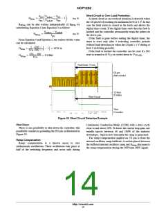
Short Circuit or Over Load Protection:
VBO Vbulkon * VBO
IBO Vbulkoff * VBO
ǒ
* 1Ǔ
RBOlo
+
(eq. 4)
A short circuit or an overload situation is detected when
the CS pin level reaching its maximum level at 1 V. In that
case the fault status is stored in the latch and allows the
digital timer count. If the digital timer ends then the fault is
latched and the controller permanently stops the pulses on
the driver pin.
R
BOup
can be also written independently of R
substituting Equation 4 into Equation 3 as follow:
by
BOlo
Vbulkon * Vbulkoff
RBOup
+
(eq. 5)
IBO
If the fault is gone before ending the digital timer, the
timer is reset only after 3 switching controller periods
without fault detection (or when the CS pin < 1 V during at
least 3 switching periods).
From Equation 4 and Equation 5, the resistor divider value
can be calculated:
370 * 1
1
10 m
ǒ350 * 1 * 1Ǔ + 5731 W
RBOlo
+
If the fault is latched the controller can be reset if a BO
370 * 350
10 m
reset is sensed or if V is cycled down to V
.
CC
CC(off)
RBOup
+
+ 2.0 MW
Fault timer: 15 ms
CS pin
(500 mV/div)
12 Vout
(5 V/div)
Short Circuit
Time
(4 ms/div)
Figure 33. Short Circuit Detection Example
Shut Down
Continuous Conduction Mode (CCM) with a duty−cycle
close to and above 50%. To lower the current loop gain, one
usually injects between 50 and 100% of the inductor
downslope. depicts how internally the ramp is generated:
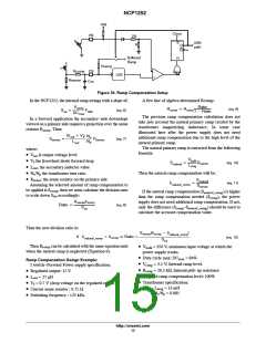
The ramp compensation applied on CS pin is from the
internal oscillator ramp buffered. A switch placed between
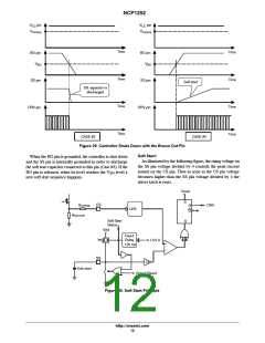
There is one possibility to shut down the controller; this
possibility consists at grounding the BO pin as illustrated in
Figure 32.
Ramp Compensation
Ramp compensation is a known mean to cure
subharmonic oscillations. These oscillations take place at
half of the switching frequency and occur only during
the buffered internal oscillator ramp and R
disconnects
ramp
the ramp compensation during the OFF time DRV signal.
http://onsemi.com
14

 ONSEMI [ ONSEMI ]