NCP1252
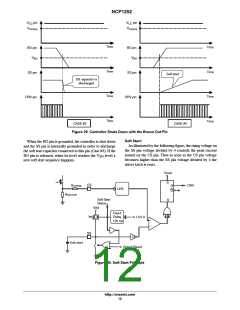
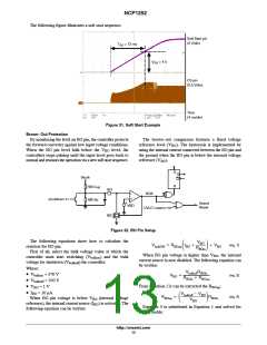
The following figure illustrates a soft start sequence.
Soft Start pin
(2 V/div)
T
SS
= 13 ms
V
SS
= 4 V
CS pin
(0.5 V/div)
Time
(4 ms/div)
Figure 31. Soft Start Example
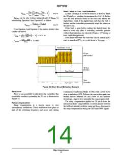
Brown−Out Protection
By monitoring the level on BO pin, the controller protects
the forward converter against low input voltage conditions.
The brown−out comparator features a fixed voltage
reference level (V ). The hysteresis is implemented by
BO
When the BO pin level falls below the V
controllers stops pulsing until the input level goes back to
normal and resumes the operation via a new soft start sequence.
level, the
using the internal current connected between the BO pin and
the ground when the BO pin is below the internal voltage
BO
reference (V ).
BO
S
R
Q
Q
Vbulk
RBOup
BO
−
BOK
+
shutdown
RBOlo
Grand
Reset
VBO
UVLO reset
IBO
Figure 32. BO Pin Setup
The following equations show how to calculate the
resistors for BO pin.
First of all, select the bulk voltage value at which the
VBO
RBOlo
ǒ Ǔ
VbulkON + RBOup IBO
)
) VBO
(eq. 1)
When BO pin voltage is higher than V , the internal
current source is now disabled. The following equation can
be written:
BO
controller must start switching (V
) and the bulk
bulkon
voltage for shutdown (V ) the controller.
bulkoff
Where:
VbulkoffRBOlo
RBOlo ) RBOup
• V
• V
= 370 V
= 350 V
• V = 1 V
VBO
+
(eq. 2)
bulkon
bulkoff
From Equation 2 it can be extracted the R
:
BOup
BO
• I = 10 mA
BO
Vbulkoff * VBO
+ ǒ
Ǔ
RBOup
RBOlo
(eq. 3)
When BO pin voltage is below V (internal voltage
BO
VBO
reference), the internal current source (I ) is activated. The
BO
Equation 3 is substituted in Equation 1 and solved for
, yields:
following equation can be written:
R
BOlo
http://onsemi.com
13

 ONSEMI [ ONSEMI ]