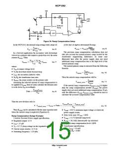
NCP1252
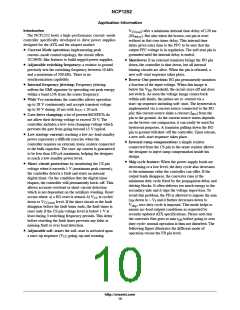
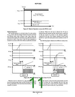
FB level
V
FBOL
= 6.0 V
Normal Operation:
DC
< DC < DC
min
maxA/B
V = 0.75 V
f
Operation @ T
on_min
DC = DC
min
V
skip
= 0.3 V
Skip: DC = 0%
Time
Figure 27. Mode of Operation versus the FB Pin Level
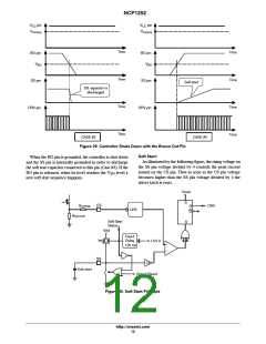
Startup Sequence:
The startup sequence is activated when Vcc pin reaches
is allowed. When the soft start is allowed the SS pin is
released from the ground and the current source connected
to this pin sources its current to the external capacitor
connected on SS pin. The voltage variation of the SS pin
divided by 4 gives the same peak current variation on the CS
pin.
V
CC(on)
level. Once the startup sequence has been activated
the internal delay timer (SS
internal delay elapses the soft start can be allowed if the BO
pin level is above V level. If the BO pin threshold is
reached or as soon as this level will be reached the soft start
) runs. Only when the
delay
BO
The following figures illustrate the different startup cases.
V
CC
pin
V
pin
CC
V
CC(on)
V
CC(on)
Time
Time
Time
Time
Time
Time
BO pin
BO pin
V
BO
V
BO
SS pin
SS pin
120 ms: Internal
delay
120 ms: Internal
delay
DRV pin
Time
DRV pin
Soft start
Soft start
No
pulse
Time
CASE #2
CASE #1
Figure 28. Different Startup Sequence Case #1 & #2
With the Case #1, when the V pin reaches the V
level, the internal timer starts. As the BO pin level is above
With the Case #2, at the end of the internal delay, the BO
pin level is below the V threshold thus the soft start
CC
CC(on)
BO
the V threshold at the end of the internal delay, a soft start
sequence is started.
sequence can not start. A new soft start sequence will start
only when the BO pin reaches the V threshold.
BO
BO
http://onsemi.com
11

 ONSEMI [ ONSEMI ]