NCP1252
V
CC
pin
V
CC
pin
V
CC(on)
V
CC(on)
Time
Time
Time
Time
Time
Time
Time
Time
BO pin
BO pin
V
BO
V
BO
SS pin
SS pin
Soft start
SS capacitor is
discharged
DRV pin
DRV pin
CASE #3
CASE #4
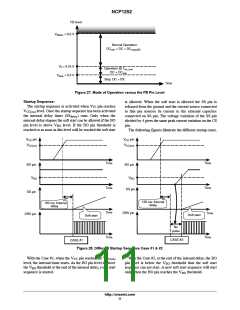
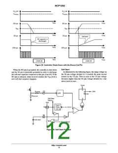
Figure 29. Controller Shuts Down with the Brown Out Pin
Soft Start:
When the BO pin is grounded, the controller is shut down
and the SS pin is internally grounded in order to discharge
the soft start capacitor connected to this pin (Case #3). If the
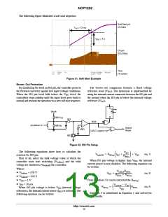
As illustrated by the following figure, the rising voltage on
the SS pin voltage divided by 4 controls the peak current
sensed on the CS pin. Thus as soon as the CS pin voltage
becomes higher than the SS pin voltage divided by 4 the
driver latch is reset.
BO pin is released, when its level reaches the V level a
BO
new soft start sequence happens.
Clock
S
CS
Q
Q
DRV
Rcomp
LEB
Rse nse
Soft Start
Status
R
Vdd
Fixed
Delay
120 ms
Iss
UVLO
+
−
SS
1/4
Grand Reset
Soft start
Figure 30. Soft Start Principle
http://onsemi.com
12

 ONSEMI [ ONSEMI ]