NCP1251
enough current (30 mA) at low line will turn a converter in
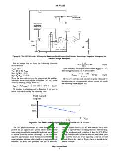
the current−sense offset. A way to reduce the power
capability at high line is to capitalize on the negative voltage
swing present on the auxiliary diode anode. During the
fault into an auto-recovery mode since the SCR won’t
remain latched. To build a sufficient design margin, we
recommend to keep at least 60 mA flowing at the lowest input
line (80 V rms for 85 V minimum for instance). An excellent
solution is to actually combine X2 discharge and start-up
networks as proposed in Figure 13 of application note
AND8488/D.
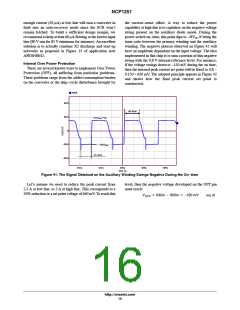
power switch on−time, this point dips to −NV , N being the
in
turns ratio between the primary winding and the auxiliary
winding. The negative plateau observed on Figure 42 will
have an amplitude dependant on the input voltage. The idea
implemented in this chip is to sum a portion of this negative
swing with the 0.8 V internal reference level. For instance,
if the voltage swings down to −150 mV during the on time,
then the internal peak current set point will be fixed to 0.8 −
0.150 = 650 mV. The adopted principle appears in Figure 42
and shows how the final peak current set point is
constructed.
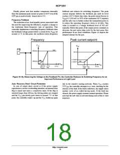
Internal Over Power Protection
There are several known ways to implement Over Power
Protection (OPP), all suffering from particular problems.
These problems range from the added consumption burden
on the converter or the skip−cycle disturbance brought by
v(24)
1
40.0
20.0
0
off−time
N (V +V )
1
out
f
1
−20.0
−40.0
−N V
2
bulk
on−time
464u
472u
480u
488u
496u
time (s)
Figure 41. The Signal Obtained on the Auxiliary Winding Swings Negative During the On−time
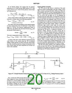
Let’s assume we need to reduce the peak current from
2.5 A at low line, to 2 A at high line. This corresponds to a
20% reduction or a set point voltage of 640 mV. To reach this
level, then the negative voltage developed on the OPP pin
must reach:
VOPP + 640m * 800m + −160 mV
(eq. 6)
http://onsemi.com
16

 ONSEMI [ ONSEMI ]